
SUSPENSION
31
INSTALLATION:
1. Proceed in the reverse order of fitment.
2. Replace rubber bushes, worn damaged parts.
3. Tighten the rear mounting bracket bolts with
proper torque.
4. Insert the lower link ballpin in to knuckle and
tighten the nut.
5. Insert the tie member and tighten the nuts.
6. Tighten the Vertical member.
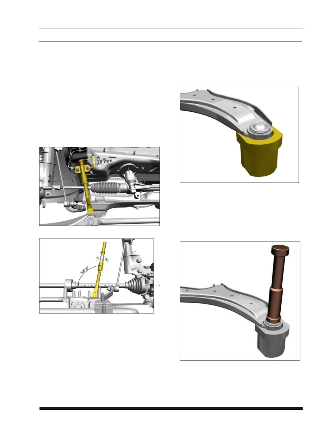
NOTE
: Ensure the position & orientation of the
Clamp of the vertical member as shown in FIG.
44a & 44b.
FIG. 44 a
FIG. 44 b
7. Ensure that heat shield is assembled properly
on ball joint
5.7.6 REMOVAL AND INSTALLATION LOWER
ARM BALL JOINT:
Removal:
a) Support (part no. 5427 5890 32 01) to be used
for ball joint removal.
FIG. 45
b) Circlip to be removed before dismantle the ball
joint assembly from control arm.
c) Push out load to be applied on sealing
periphery (peened area) using special tool (part
no 2834 5890 2614) without contacting the
back plate.
FIG. 46


