
1.05L REVOTORQ ENGINE
103
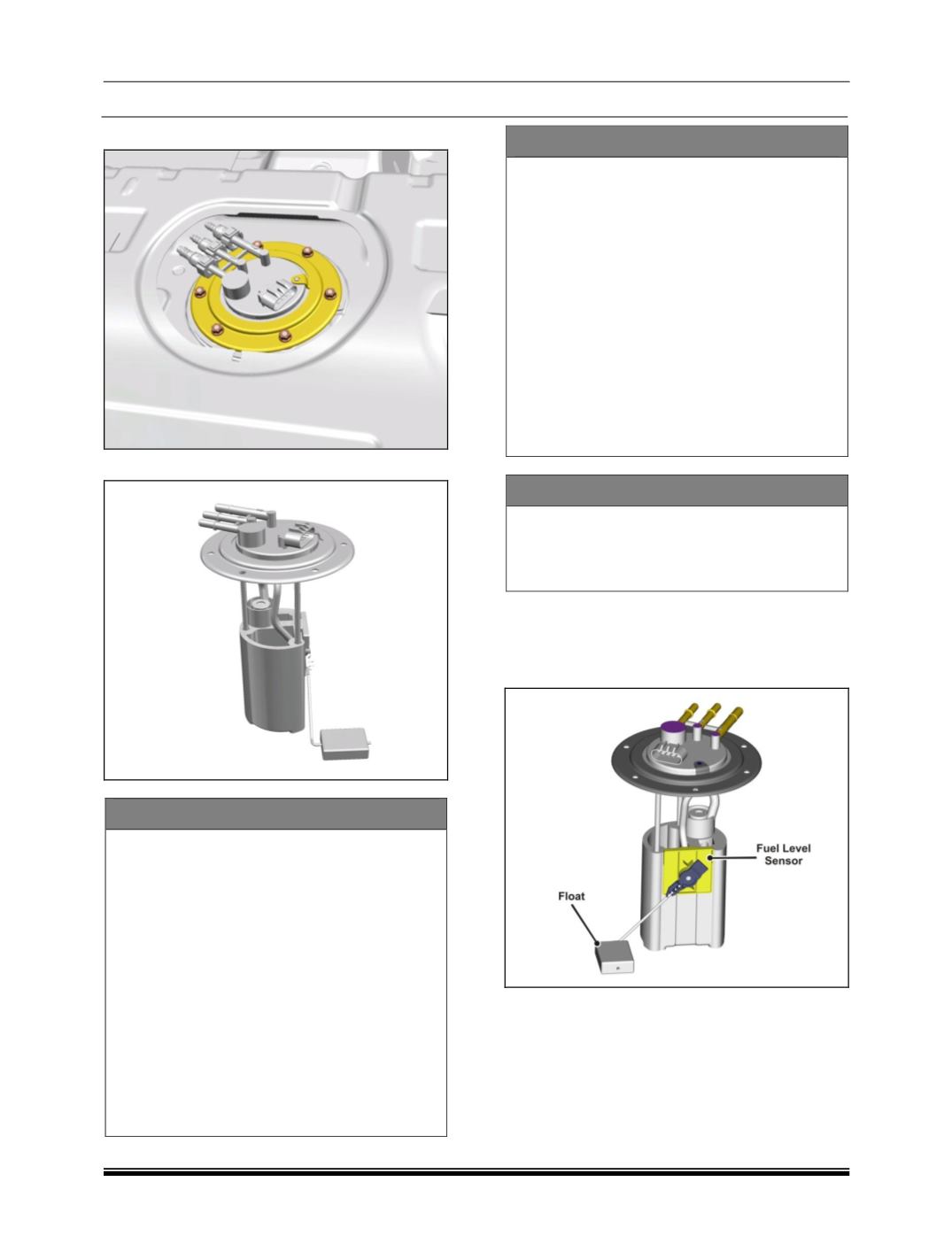
5. Loosen and remove the 6 mounting nuts.
6. Lift the in-tank pump carefully out
NOTE
The fuel module shall consist of level
sensor, sealing ring and locking ring.
The material of the FSU seal shall be
HNBR as per SS:5565
Pump should have a flexibility in orientation
atleast for two positions.
Electrical cables and hoses connecting
pumps and flange should not be protrude
outside the diameter.
The float orientation to be decided by party
for better performance.
Be free from flash, Flaw, Rust and Concave
on joining and sealing surface.
Be free from foreign body in fuel passage.
ASSEMBLY
Don't hold the fuel pump unit by tubes,
wires, fuel level sensor unit.
Remove the protection cap only before
assembly of the hydraulic connector.
The fuel pump unit only has to be fixed at
the outer diameter of the tank flange during
assembly into fuel tank.
During transport of the tank with assembled
fuel pump unit. It is absolutely necessary to
protect the tubes with protective caps
against dirt, particles etc.
Return line of vehicle has to be clean.
Hydraulic protection cap : Protection only
against dust and splash water
CONDITION OF USE
Minimum tank filling height for start of the
engine after first filling equal to 25 mm from
bottom of reservoir. (Only valid for
horizontal tank bottom)
E. Fuel Level Sensor :
Removal :
1. Remove the tank unit.
2. Disconnect the connector.
3. Remove the fuel level sensor by releasing the
snaps.
Fuel Level Sensor Specification :
Vehicle operating voltage : 12V DC with -ve
ground
Operating voltage : 8V to 16V


