


 305 / 310

ELECTRICAL
15
CONNECTOR DETAILS:
A Connector
SR. NO.
DISCRIPTION
1
Left front Low +
2
Right front Low +
3
Left front High +
4
Right front High +
5 - 8
NC
9
Left front Low -
10
Right front Low -
11
Left front High -
12
Right front High -
13 - 16 NC
B Connector
SR. NO.
DISCRIPTION
1
Subwoofer +
2
Center +
3
Left Rear +
4
Right Rear +
5
NC
6
Amp Enable (ON/OFF)
7
Right Rear +
8
Left Rear +
9
Right Front In +
10
Left Front In +
11 - 13 B +
14
Subwoofer -
15
Center -
16
Left Rear -
17
Right Rear -
18
Mute On/Off
19
Speed
20
Right Rear In --
21
Left Rear In --
22
Right Front In -
23
Left Front In +
24 - 26 GND
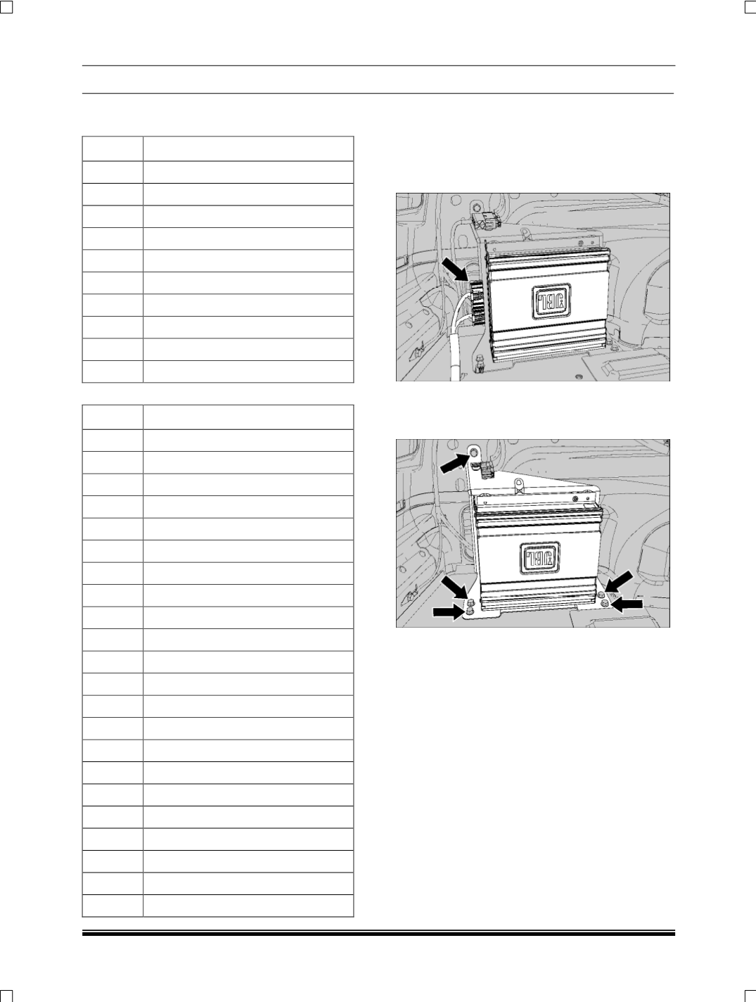
REMOVAL:
1.Remove the rear quarter trim LH (
Refer body
section).
2.Disconnect the electrical connection of audio
amplifier.
3.Loosen and remove the four mountings screws
on Floor and one on rear quarter panel LH to
take out the amplifier with bracket.
REFITMENT
1.Assemble the Bracket and amplifier together with
four self tapping screws.
2.Connect the electrical connections.
3.Fit the Audio Amplifier with four screws on floor
and one on quarter panel.
Tightening torque for screws – 0.3 Kgfm
4.Fit the rear quarter door trim LH (
Refer body
section).