


 326 / 1526

24
TRANSFER CASE
100. ELECTRIC SHIFT CAM
101. TORSION SPRING
102. SPACER
103. SHIFT SHAFT
ASSEMBLY
General Instructions
:
* Use special tool for assembly of oil seals and
bearings.
* Lubricate bearings, oil seals, O-rings,
bushings and matching metal parts before
assembly.
* Always replace the hose coupling, O-ring and
oil seal.
* For torque values refer torque table.
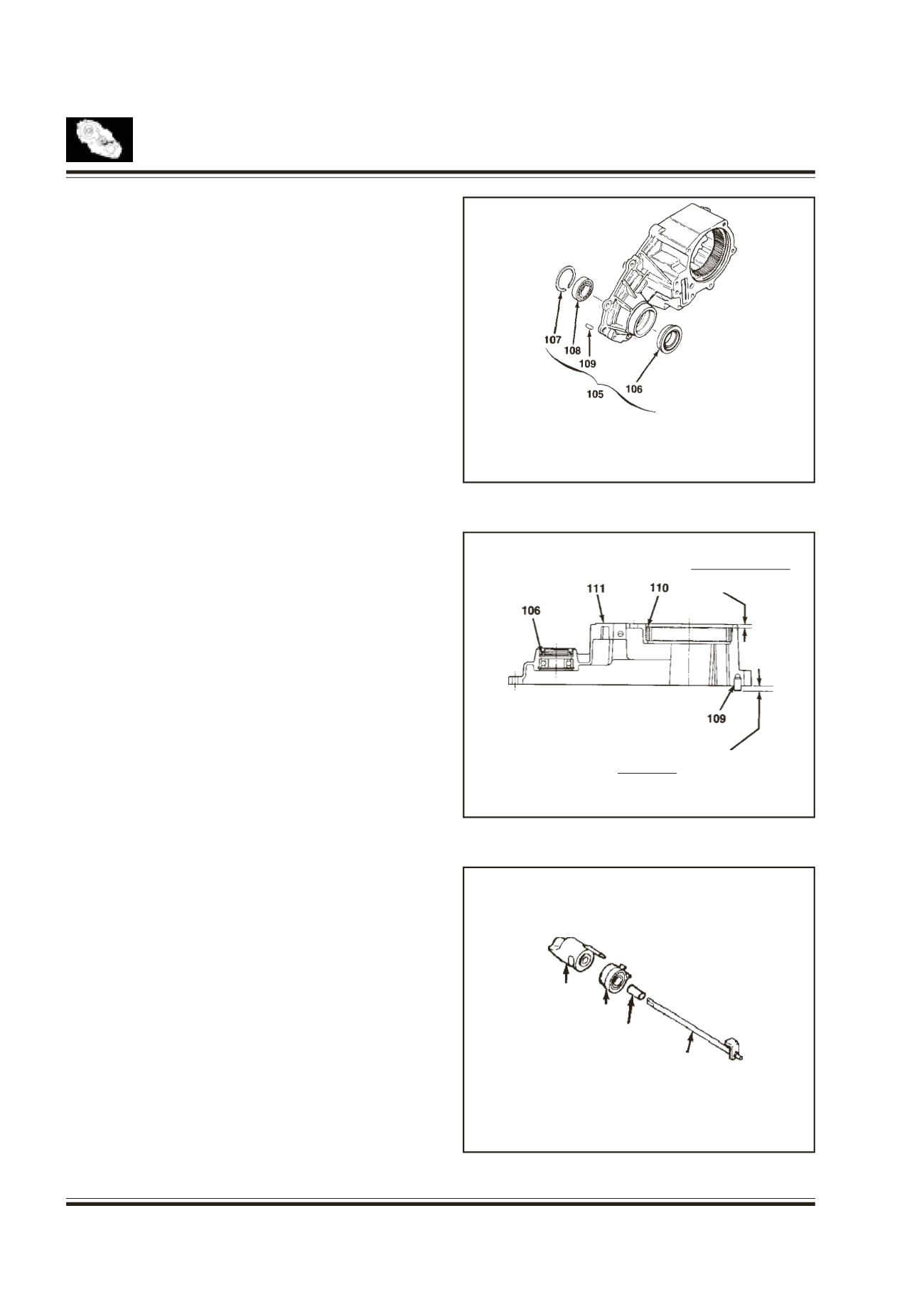
Transfer Case
Fig. 19 & 20
Insert the two new dowel pins.
Insert the ball bearing into the case and install the
retaining ring (snap ring).
Install the new oil seal, by pressing it into the case.
Make sure that all parts are correctly and firmly
installed into the case.
105. TRANSFER CASE
ASSEMBLY
106. OIL SEAL
106. OIL SEAL
109. DOWEL PIN
110. RING GEAR
.380 IN.
111. TRANSFER CASE (9.65 MM)
107. RETAININGRING
108. BALL BEARING
109. DOWEL PIN
Fig. 19
Fig. 20
Fig. 21
.242 IN. (6.16 MM)
.222 IN. (5.65 MM)
- 2 PLACES
Electric Shift Cam Parts
Fig. 21
Insert spacer into torsion spring.
Insert end of the shift shaft into the spacer.
100
101
102
103