


 332 / 1526

30
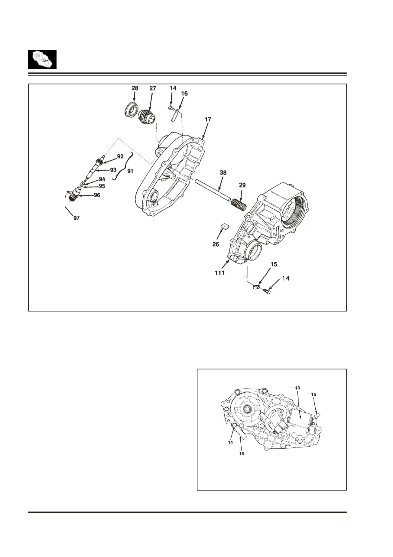
TRANSFER CASE
14.
BOLT
15.
WIRING CLIP
16.
IDENTIFICATIONTAG
17.
COVER ASSY
26.
MAGNET
27.
SPEEDO GEAR
28.
OIL SEAL
29.
RETURN SPRING
38.
RAIL SHAFT
Install the cover into the transfer case as follows:
Refer fig. 36
* Align the cover holes with the transfer case
dowel pins
* Align the cover bearings with output shafts.
* Align the cover blind hole with rail shaft and make
sure that return spring is not cocked
Tighten nine bolts positioning identification tag and
wiring clip
Install the speedo gear over output shaft spline in the
cover assembly
Press the new oil seal into the cover assembly.
The indication tag is attached to the transfer case at
the location shown in the figure. The manufacturing
details are stamped on the tag. This information is
necessary for ordering replacement spare parts.
Fig. 37.
The identification tag explanation is given in general
group.
91.
SPEEDO ASSY
92.
GEAR SPEEDO
93.
SHAFT SPEEDO
94.
SEAL
95.
O RING
96.
BODY SPEEDO
97.
BOLT
111.
TRANSFER CASE
13. MOTOR ASSY.
14. BOLT
15. WIRING CLIP
16. IDENTIFICATION TAG
Fig. 36
Fig. 37