


 329 / 1526

27
TRANSFER CASE
After pressing in the bearing, install the retaining ring.
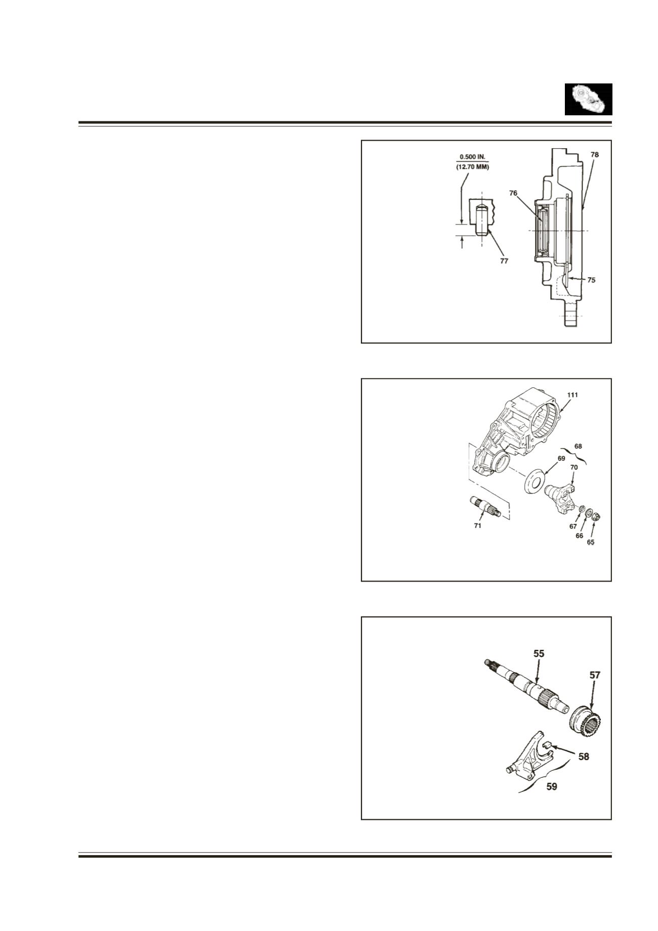
Press the pin into the front adapter.
Press the oil seal into the front adapter.
Fig. 27
Install the front adapter assembly.Make sure that snap
ring is correctly installed into the groove.
Position the input shaft assembly over front cover and
engage into bearing groove by expanding the ends of
snap ring.
Apply about 1.6 mm bead of sealant on the mounting
face for the transfer case and tighten the six bolts.
Install the breather.
Front Output Shaft
Fig. 28
Press the deflector onto yoke
Position the output shaft in transfer case and install
the end yoke assembly, seal, washer and nut by
holding the end yoke, tighten the nut.
Reduction Shift Parts
Fig. 29
Install new pin, roller into the reduction shift fork.
Press the pin, roller into the reduction shift fork bore.
Ensure that the cam roller turns freely.
Install the two fork facing on the reduction shift shaft
assembly.
Install the reduction shift fork onto previously installed
reduction hub in the transfer case.
Install the output shaft spline into the reduction hub
and engage the output shaft end with input shaft
bearing.
75. SNAP RING
76. OIL SEAL
77. SPIRAL PIN
78. FRONT ADAPTOR
65. NUT
66. WASHER
67. SEAL
68. YOKE ASSY
69. DEFLECTOR
70. YOKE
71. OUTPUT SHAFT (FRONT)
111. TRANSFER CASE
55. OUTPUT SHAFT
57. REDUCTION
HUB
58. SHIFT FORK
FACING
59. REDUCTION
SHIFT FORK
ASSY
Fig. 27
Fig. 28
Fig. 29