


 322 / 1526

20
TRANSFER CASE
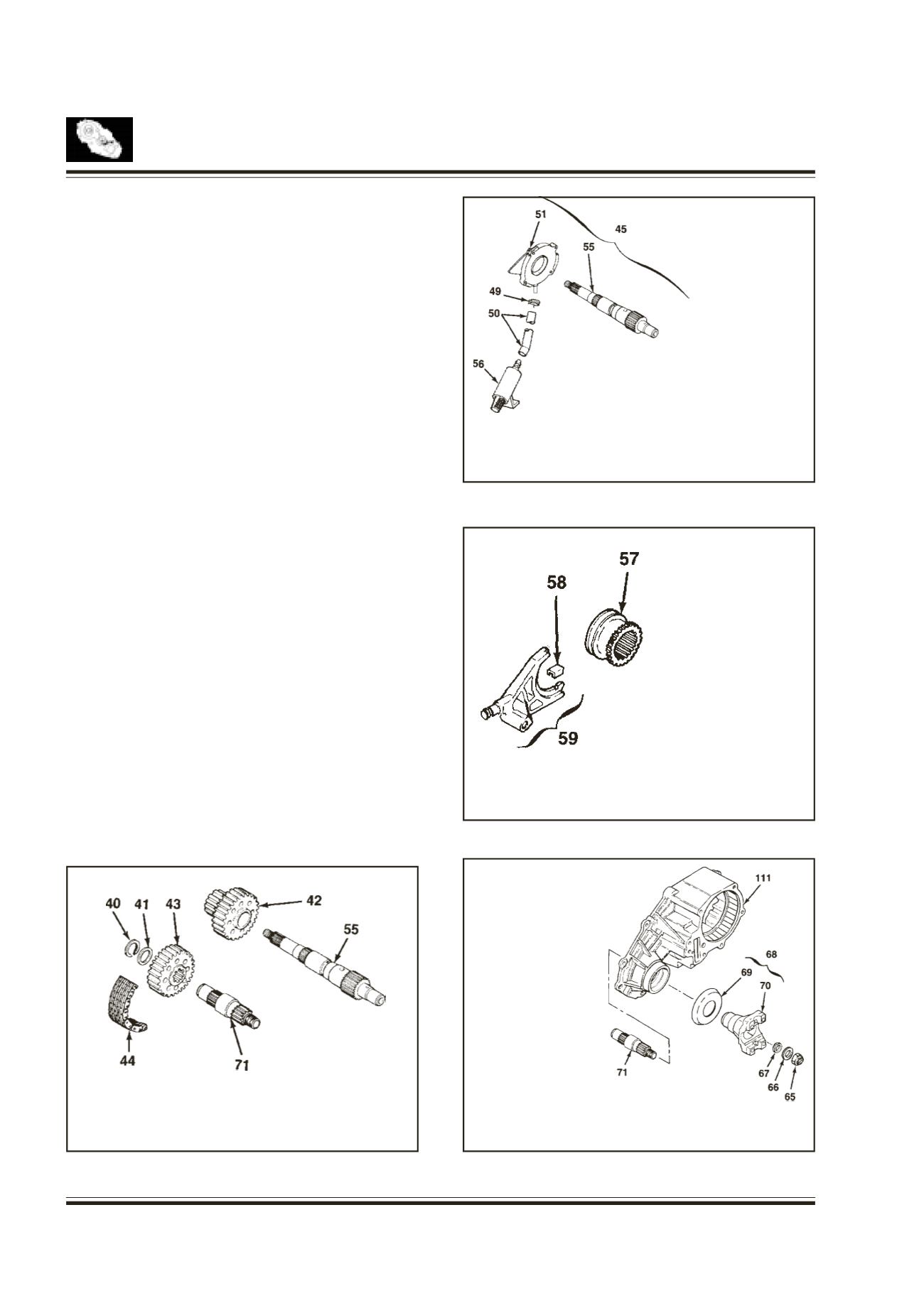
45.
SHAFT & PUMP ASSY
49.
HOSE CLAMP
50.
HOSE COUPLING
51.
PUMP ASSEMBLY
54.
FRONT PUMP COVER
55.
OUTPUT SHAFT
56.
STRAINER
57. REDUCTIONHUB
58. SHIFT FORK FACING
59. REDUCTION SHIFT FORK
ASSY
Drive Chain
Fig. 10
Remove snap ring and spacer from the output shaft.
Remove drive chain, driven sprocket and drive
sprocket from the output shaft.
Separate the chain and sprocket when removing the
assembly.
Gerotor Pump Assembly
Fig. 11
Loosen the hose clamp and remove the hose
coupling from the pump housing.
Remove hose clamp hose coupling and strainer.
Slide the Gerotor pump off the output shaft and
remove the output shaft.
Separate the pump and output shaft.
Reduction Shift Parts
Fig. 12
Remove the reduction hub and reduction fork
assembly from the case.
Remove the two shift fork facings form the shift fork
assembly.
Front Output Assembly
Fig. 13
Holding the end yoke with yoke holder, remove the
nut and washer and then remove the end yoke and
seal.
Separate the end yoke and deflector and remove the
output shaft.
40. SNAP RING
41. SPACER
42. DRIVE SPROCKET
43. DRIVEN SPROCKET
44. DRIVE CHAIN
55. OUTPUT SHAFT (REAR)
71. OUTPUT SHAFT
(FRONT)
Fig. 10
Fig. 11
Fig. 12
Fig. 13
65.
NUT
66.
WASHER
67.
SEAL
68.
YOKE ASSY
69.
DEFLECTOR
70.
YOKE
71.
OUTPUT SHAFT (FRONT)
111.
TRANSFER CASE