


 330 / 1526

28
TRANSFER CASE
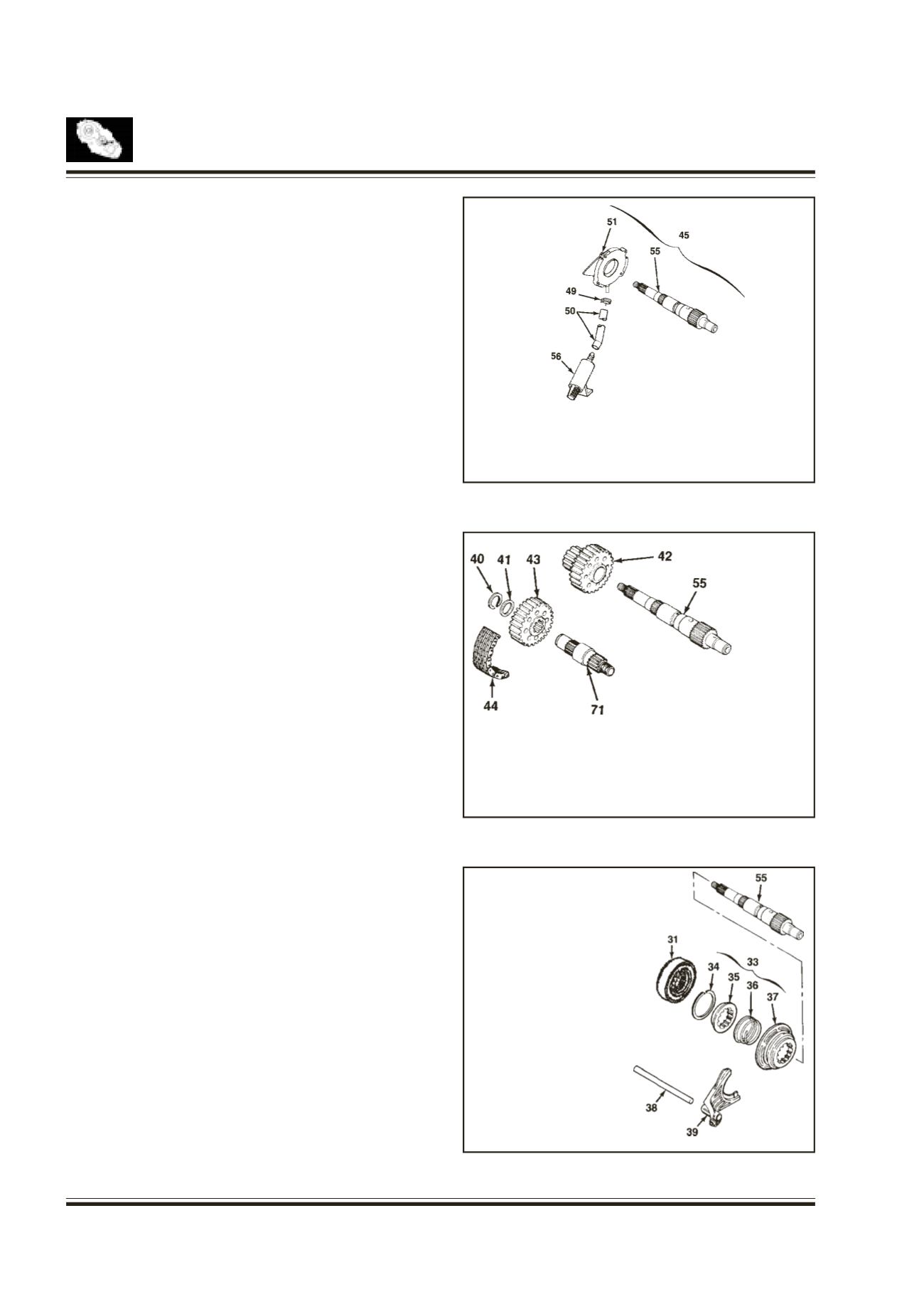
Gerotor Pump Assembly
Fig. 30
Fit the pump pin in the output shaft.
Slide the pump assembly on the output shaft over
pump pin.
Slip hose clamp over free end of hose coupling with
strainer and push onto hose barb on pump and tighten.
Drive Chain
Fig. 31
Position the drive sprocket to the rear output shaft
end and driven sprocket to the front output shaft end.
Install the drive chain onto the sprocket.
Holding each sprocket with drive chain tight and
parallel with transfer case, install the drive chain
assembly to the output shafts.
Rotate the driven sprocket slightly to engage splines
on the front output shaft.
Install the spacer to the front output shaft and insert
the snap ring into the groove over spacer.
Lockup Shift
Fig. 32
Install the lockup hub and return spring to the lock up
collar and insert the snap ring.
Install the rail shaft through reduction shift fork
assembly previously installed and into the blind holes
in case.
Engage the lockup fork in 2WD-4WDgroove and check
operation.
45. SHAFT & PUMP ASSY
49. HOSE CLAMP
50. HOSE COUPLING
40. SNAP RING
41. SPACER
42. DRIVE SPROCKET
43. DRIVEN SPROCKET
44. DRIVE CHAIN
55. OUTPUT SHAFT (REAR)
71. OUTPUT SHAFT (FRONT)
51. PUMP ASSEMBLY
55. OUTPUT SHAFT
56. STRAINER
Fig. 30
Fig. 31
Fig. 32
31. CLUTCHHOUSING
33. 2W-4W LOCKUP ASSY
34. SNAP RING
36. RETURN SPRING
37. LOCKUPCOLLAR
38. RAIL SHAFT
39. LOCKUP FORK
55. OUTPUT SHAFT