


 1260 / 1526

ENGINE
92
Fig. 21
Fig. 22
Fig. 23
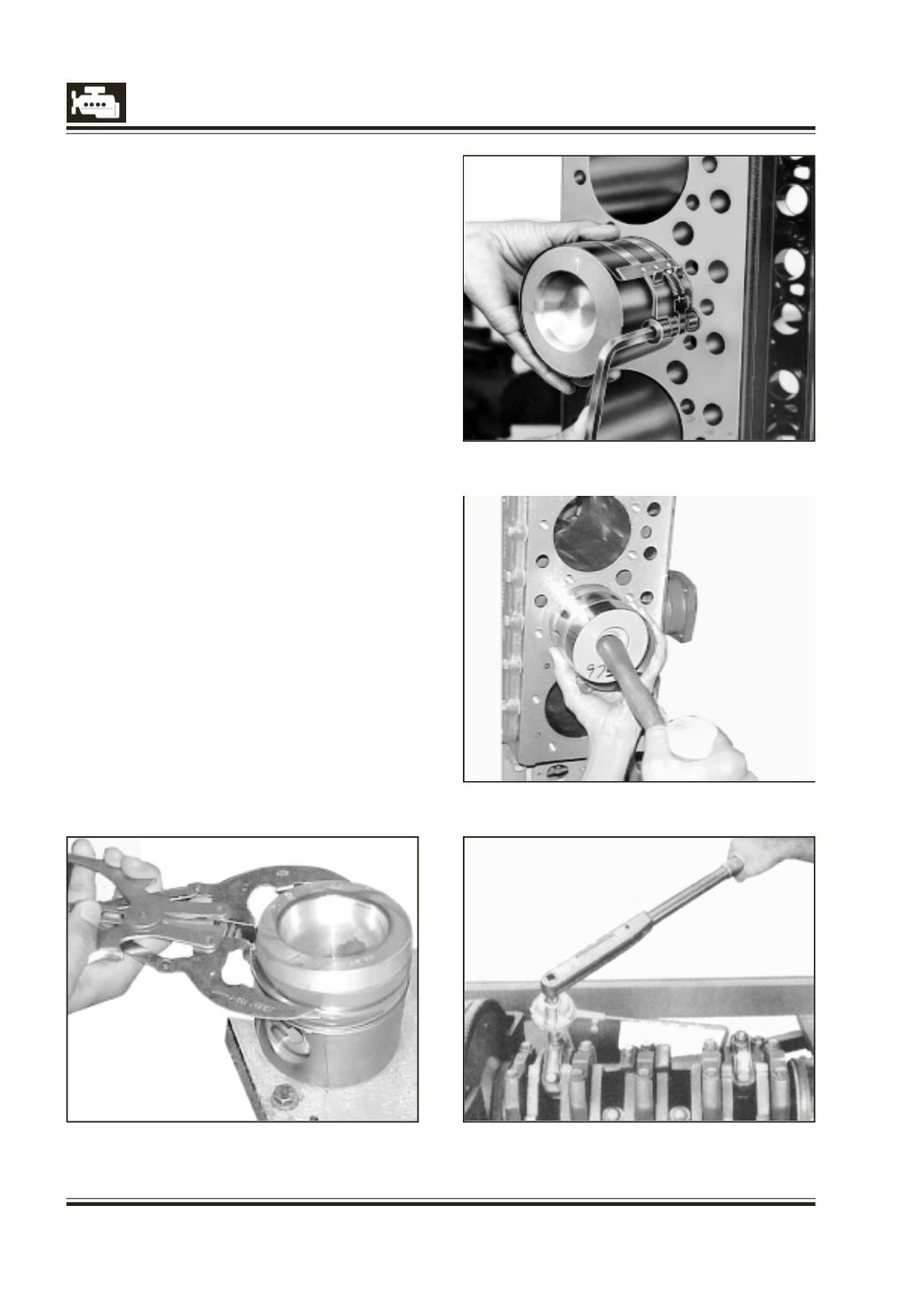
Fig. 20
10 Stagger piston ring gaps such that they are 180
deg apart. Clamp piston ring compressor over
piston rings upto out side diameter of piston so
that it can slide over it with little force. Fig. 21.
Push piston assembly in cylinder bore gradually
by using mallet handle till connecting rod locates
on crankpin. Fig. 22. Now rotate crankshaft slowly
and simultaneously pushing piston assembly till
the crankpin reaches bottom most position.
11 Install connecting rod cap with bearing, on
connecting rod ensuring that identification
number of connecting rod as well as on cap are
matched and bearing shell lugs are on same side.
Hand tighten connecting rod cap fasteners.
12 Assemble remaining piston - connecting rod
assemblies in same manner.
13 Turn crankshaft and bring any one pair of pistons
to BDC. Tighten fastening bolts of this pair with
torque wrench to specified torque. Fig. 23.
14 Similarly tighten remaining connecting rod bolts.
15 Check connecting rod axial play or side clearance
and distance between piston crown (at TDC) and
cylinder block top surface. These should be within
specified limits.
16 Check free running of connecting rod bearing.
When crankpin and connecting rod bearing
dimensions are maintained within specified
values, running clearance between crankpin and
bearing is automatically ensured.