


 1255 / 1526

ENGINE
87
Fig. 14
Fig. 15
Fig. 16
REMOVAL OF VALVE SEAT INSERTS
For both inlet and exhaust valves, valve seat inserts
are standard fitment. They are shrunk and then
pressed in cylinder head. Therefore, removal of valve
seat inserts should be done only if they are damaged
beyond repair or worn out beyond specified limits.
1 For removing seat inserts from cylinder head, use
suitable boringmachine. Bore old insert thin (about
0.5 mm thickness) and then try it out.
2 Alternatively, use a suitable turning tool to cut an
angular groove into seat insert and then pull it
out with a suitable puller. In order to avoid
damaging of machined cylinder head parting
surface, place copper or any other protective
sheet-metal under puller supports.
3 Measure basic bores for valve seat inserts with
bore gauge. If the boring and prying is done
carefully without damaging the parent bore of
the inserts, fitment of an oversize insert will
normally be not necessary. However, if the parent
bore dimensions deviate from the values
specified, enlarge bore to the next repair size. This
should done on a suitable fine boring machine.
4 Re-machined bore must exactly be at right angles
to the cylinder head surface and the bore size
should be strictly within specifications so as to
ensure proper interference fit of the inserts.
5 Clean basic bores in cylinder head and seat inserts
thoroughly before fitting.
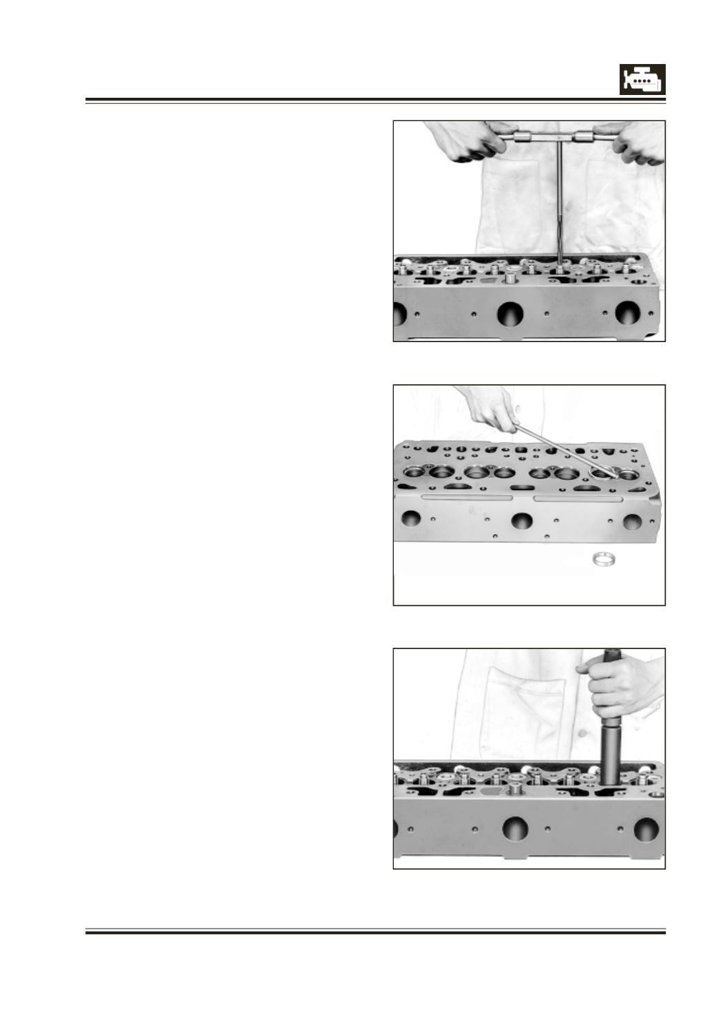
INSTALLATION OF VALVE SEAT INSERTS
1 Place valve seat inserts in liquid oxygen for about
20 to 30 minutes to bring their temperature down
to - 195 deg C (when liquid oxygen stops no longer
producing 'vapour' and stops spurting, valve seat
inserts have a temperature of approximately - 195
deg C). If liquid oxygen is not available, keep
inserts in ice and salt mixture for about 6-8 hours.
CAUTION
Do not touch liquid oxygen or chilled valve seat
inserts with your fingers. Use a pair of tongs.
2 Heat cylinder head to approx. 80 deg C in a water
bath.
3 Take seat inserts out of liquid oxygen by using
tongs and place on bore of heated cylinder head
(Fig. 15). Install them quickly by slight hammering
with the help of a drift. Fig. 16.
4 After inserting seat inserts, check distance
between parting surface of cylinder head and
face of valve seat insert. If necessary, re-machine
the face with an end mill/suitable cutter.
5 Machine valve seats as per specifications.