


 1263 / 1526

ENGINE
95
Fig. 8
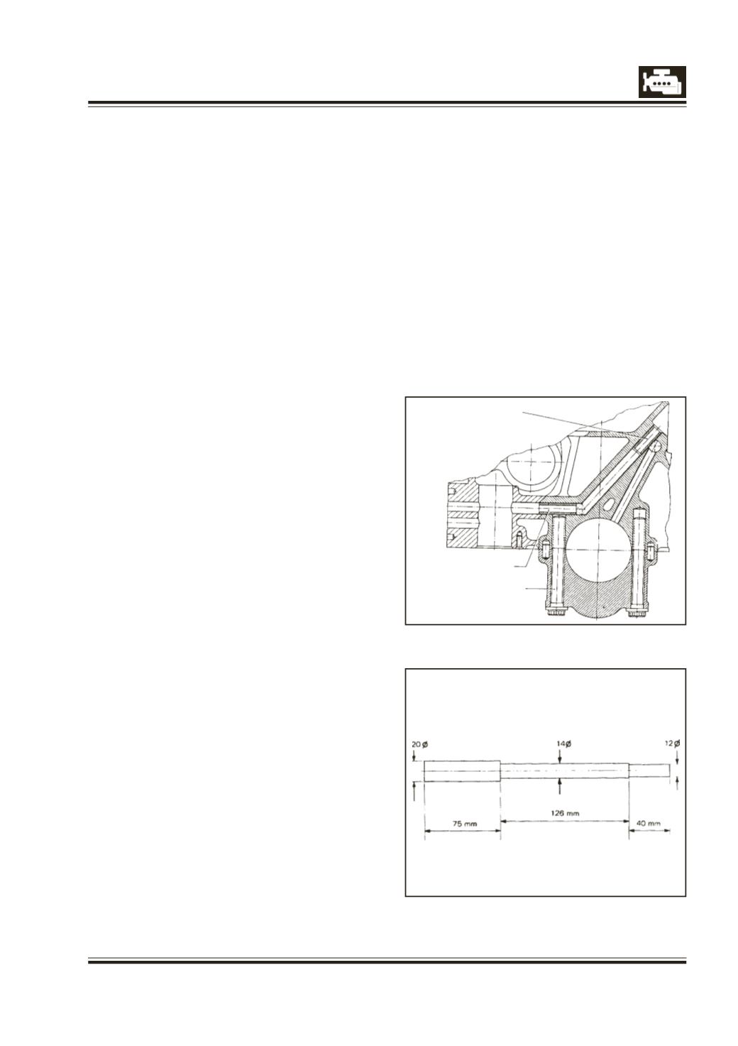
Fig. 7
MAIN BEARING CAP
BOLT
TUBE
3 Do not smear parent bore or liner outer diameter
with oil.
4 Place liner in parent bore and make it at right
angles to cylinder block surface in longitudinal and
perpendicular planes using precision tri-square.
5 Press liner using drift, 2651 5890 02 02 ensuring
that ram is seating squarely on the drift.
Note: Fully pressed in liner protrudes beyond block
face by 0.5 to 0.6 mm. Utmost care should be
exercised at the end of liner pressing. To make sure
that the liner is pressed fully home, load should be
applied very carefully with fine increments.
Subjecting liner under high pressure at this stage
may result in cracking of the liner at the collar.
6 Similarly press all remaining liners.
CYLINDER BORE MACHINING
1 Machine all bores to 96.93 to 96.95 mm dia.
leaving 0.05 to 0.07 mm stock for honing.
2 Using a face cutter tool, machine off protrusion of
liner to make it flush with the block surface.
Machine a chamber of 0.5 mm x 45 deg on I.D. of
the liners.
The honing should be done in two stages as
follows:
Stage I
Use honing stone of grit 180. The honing speed
should be approx. 100-120 rpm and approx. 60
double strokes per minute and length of stroke
130 mm. Under these conditions, a cross hatch
angle E of approx. 45 to 60 deg is obtained.
Leave only 0.01 mm material for the 2nd stage
honing.
Stage II
In the 2nd stage of honing, use honing stone of
grit 240. The honing speed should be approx.
50-60 rpm, with 30 double strokes per minute and
130 mm stroke length.
With this, a cross hatch angle of approx. 45 deg
to 60 deg is obtained.
NOTE
1.
It is very important that the axis of the cylinder
bores are parallel to each other and are at right
angles to axis of crankshaft. Therefore, we
recommend the use of pillar type boring and
honing machines in preference to portable type
boring bar and honing machines. If the portable
boring bar must be used, check and clean mating
surface of the boring bar and cylinder block, and
centralise the boring bar as accurately as possible.
2 Clean cylinder block thoroughly and apply grease
on machined surfaces of cylinder block especially
if the engine assembly is not to be taken up
immediately.
3.
Adjust hone travel to ensure that the honing tool
projects by approx 20-25 mm from the top and
bottom during honing. Use plenty of kerosene for
this operation.
i
v. OIL PASSAGES
1 Clean all oil passages thoroughly by using suitable
wire brushes/compressed air.
2 Tubes shown in Fig. 7 prevent leakage of engine
oil through main bearing bolts or oil passage to
main oil gallery.
If necessary, new tubes may be fitted with the
drift as shown in the Fig. 8.