


 1259 / 1526

ENGINE
91
Fig. 18
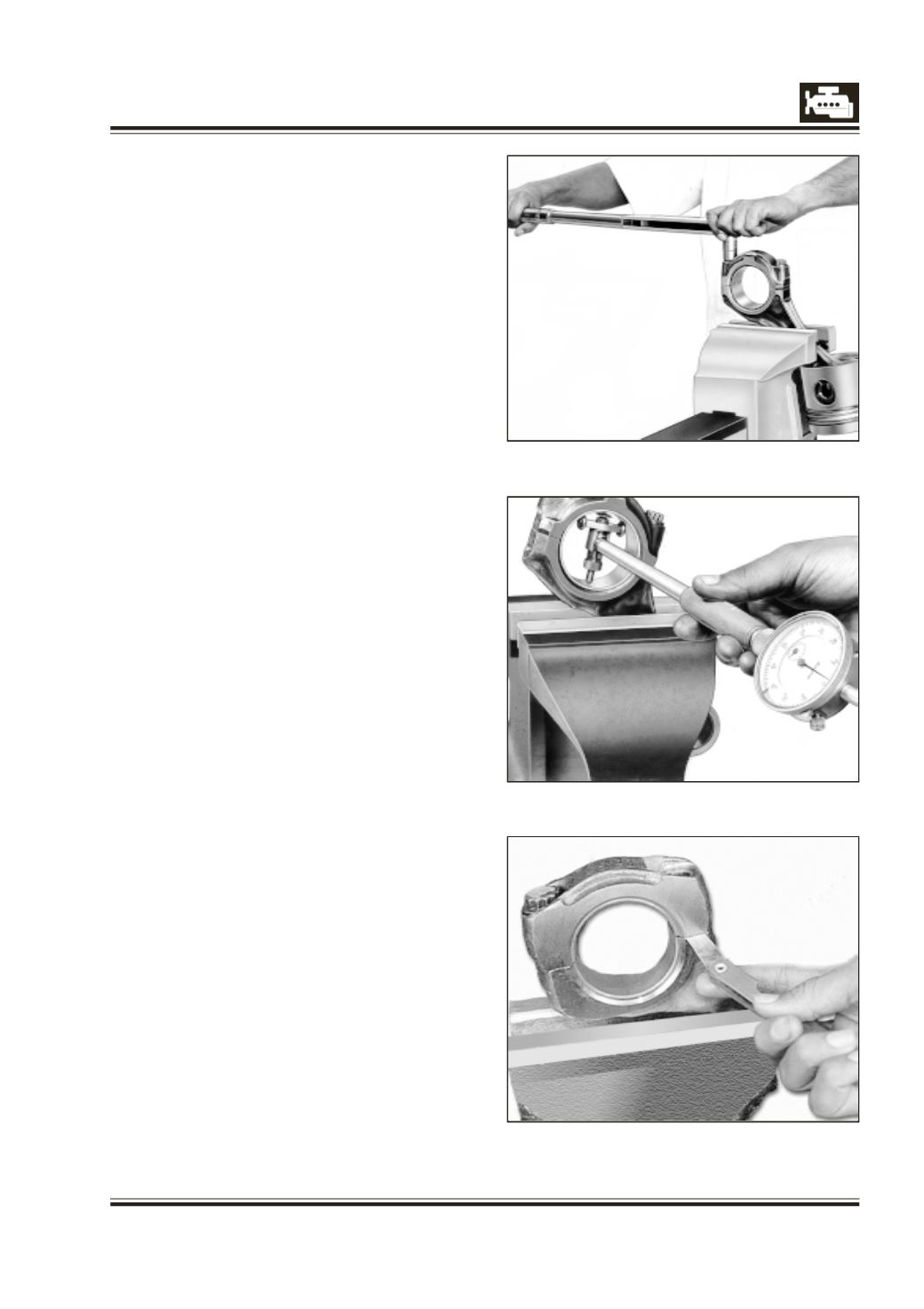
Fig. 19
Fig. 17
NOTE
:
If big end parent bore diameter is maintained
within specifications, proper bearing dimension
is automatically achieved. However, it must be
ensured by physically checking the bearing size.
15 Measure pretension of bearing with a feeler gauge
after loosening cap bolt, opposite to bearing shell
lug. Fig. 19.
16 Remove connecting rod bearing caps.
NOTE :
Connecting rod bearing shells, no matter of which
repair stage, are precision finished and must on
no account be bored or scraped.
INSTALLATION OF PISTONS AND CONNECTING
RODS
1 Clean piston, connecting rod, piston rings and
bearing shells.
2 Warm up piston in hot oil at 70 deg C to 80 deg C.
3 Insert connecting rod in piston such that face of
connecting rod on which an arrow mark is
stamped will come on same side of arrow on
piston.
4 Insert piston pin quickly. Fit circlips using suitable pliers.
5 Assemble piston rings using piston ring expander
from top of the piston starting from 3rd groove.
Fig. 20. Ensure that ‘TOP’ mark on 2nd ring faces
piston crown.
6 Assemble bearing shells in connecting rods/caps
making sure that locating lugs of the shells are
properly seated.
In case old bearings are being reused, install marked
shells in their respective connecting rods/Caps.
7 Oil piston, bearing bores and cylinder bores.
8 Turn crankshaft and bring the crank pin onto which
connecting rod is to be assembled to top most
position.
9 Insert connecting rod with piston into cylinder
bore with arrow on piston crown pointing towards
front (forward driving direction) and arrow on
connecting rod would point towards oil cooler.