


 1258 / 1526

ENGINE
90
Fig. 13
Fig. 14
Fig. 15
Fig. 16
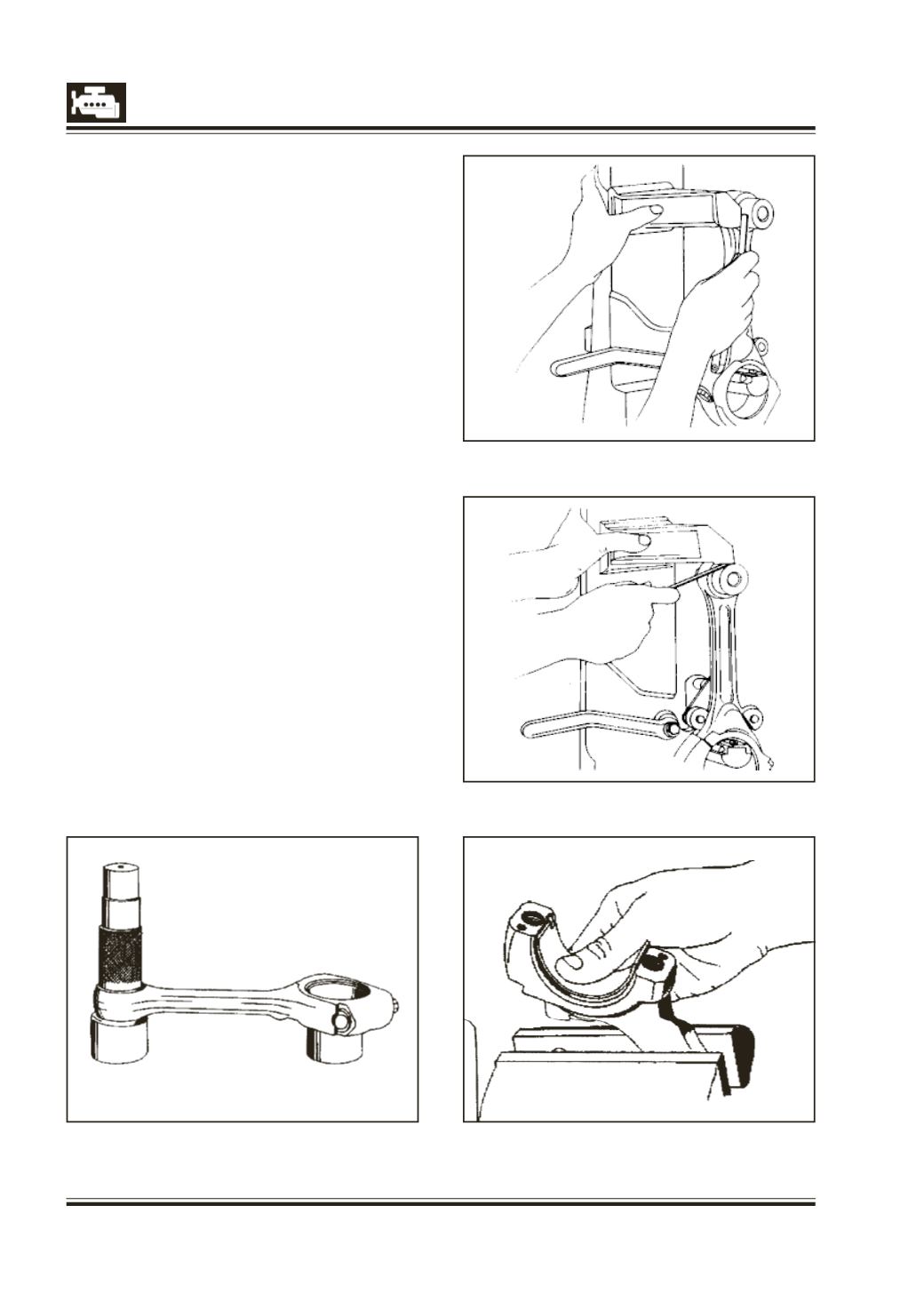
7 Check twist and bend of connecting rod by using
new piston pin in small end bush. Measure twist
and bend of connecting rod with a feeler gauge
with respect to vertical face of connecting rod
alignment gauge in vertical and horizontal planes
and at a distance of 50 mm from the joining centres
of small end and big end bosses. Fig. 14 & 15.
8 If necessary, straighten connecting rod in cold
condition.
9 Check connecting rod big end parent bore.
10 If diameter of connecting rod big end parent bore is
slightly more than maximum permissible limits, it is
possible to reclaimconnecting rodprovidedthatwear
is confined only to cap. Connecting rod can mating
surfacemaybe slightly facedandparent bore finished
ona connecting rodboringmachine.However,centre
to centre distance between small end and big end
bores should be strictly as specified.
11 If one or more connecting rods are to be replaced,
ensure that the difference in weights of the
connecting rods in one engine is within permissible
limits. (Max. difference in weight 10 gm).
12 Fit newpair of connecting rodbearingshell according
to size of crank pin, making sure that securing lugs of
bearingshells areproperly seated ingroovesof parent
bore of connecting rod and cap. Fig. 16.
13 Place bearing cap with bearing shell on
connecting rod, tighten and torque fastening bolts
(preferably use new bolts) with torque wrench to
specified value. Fig. 17.
14 Measure connecting rod bearing bore with bore
measuring gauge at three points as shown. Fig. 18.