


 1264 / 1526

ENGINE
96
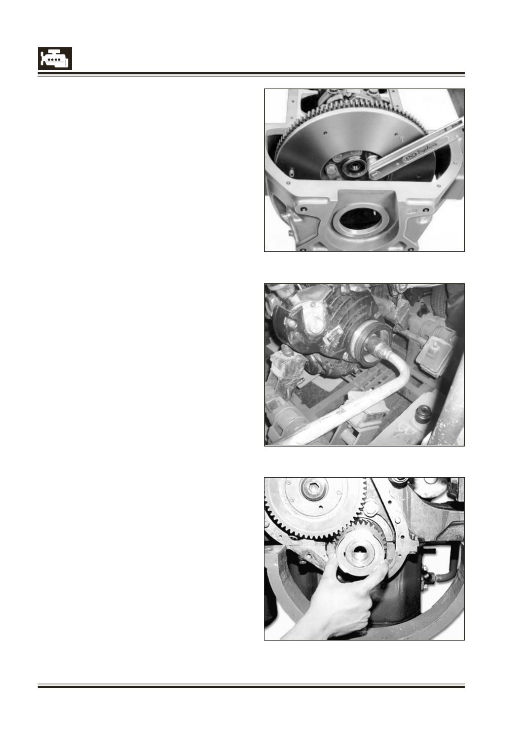
Fig. 1
Fig. 2
Fig. 3
FLYWHEEL/RING GEAR/CRANKSHAFT PULLEY
REMOVAL OF FLYWHEEL
(Clutch removed)
1 Remove speed sensor on clutch housing.
2 Lock flywheel suitably.
3 Unlock lock plates and unscrew fastening bolts
from flywheel.
4 Tap with plastic mallet and remove flywheel.
INSTALLATION OF FLYWHEEL
1 Position flywheel on crankshaft flange.
2 Align all holes on flywheel with tapped holes of
crankshaft flange.
3 Place new lock plates and screw in flywheel mounting
bolts after oiling their threads.Tighten them uniformly
cross-wisetospecifiedtorque. Fig. 1.
4 Lock flywheelmounting screws by staking lockplates
on bolt heads.
5. Fit thespeedsensor andtightenwithspecifiedtorque.
INSPECTION AND REPAIR OF FLYWHEEL
1 Check starter ringgear forwear anddamage. Replace
if necessary.
2 Clean flywheel and check for cracks, scoring, burns
and unevenness.
3 If necessary, grind friction face just to clear defect
after removing dowels meant for pressure plate.
Grinding should be done over entire friction face. In
any case, thickness of flywheel shouldnot be reduced
beyond specified limit. Fix new dowels.
REPLACEMENT OF STARTER RING GEAR
(Flywheel removed)
1 Quickly heat starter ringgear withwelding flame and
press it out.
2 Heat new ring gear to 180 deg C – 230 deg C (Yellow
annealing colour). Press in ring gear upto contact
surface of flywheel.
3 Maximum lateral runout of ring gear should not
exceed specified value after pressing.
REMOVAL OF CRANKSHAFT PULLEY
1 Slacken and remove V-belt driving water pump/
alternator.
2 Lockcrankshaft at flywheel suitablyandremovepulley
mounting bolt. Fig. 2.
3 Mount suitable two leg puller with spacer & pull
out the pulley.
4 Examine woodruff key and replace if necessary.
5 Remove oil slinger (if fitted).