
1.05L REVOTORQ ENGINE
121
7.
Clean valve seat insert and its bore in cylinder
head thoroughly.
F. Just Before Installation :
1.
Place valve seat insert in mixture of Methanol
and dry ice for about 20-30 minutes to bring
temperature down to -150ºC.
2.
Heat cylinder head to approximately 80ºC in
hot water bath.
3.
Install valve seat insert in cylinder head bore
quickly by light hammering.
4.
Machine valve seat in cylinder head.
G. Cam Shaft :
1.
Check cam shaft run out at 2nd journal by
supporting it on V-block at 1st and 3rd journal.
2.
Check cam shaft journal dimensions. Record
the readings.
3.
Carry out visual inspection of cam shaft for:
•
Overheating of journals, this is indicated by
bluish/ brown colour.
•
Deep scoring marks on journals and cam
lobes
•
Cracks, which should be checked on a
magnetic crack detector.
4.
Check hardness of cam shaft journals and cam
lobes, it should be 47 HRC.
H. Hydraulic Lash Adjuster :
Hydraulic Lash Adjuster supports the pivot end of
the rocker arm while automatically controlling the
rocker arm position to keep it in contact with the
camshafts and valve.
The range of the hydraulic lash adjuster
accommodates engine build tolerances; hence no
adjustment is required during engine assembly. It
also compensates for variation that occurs during
the life of the engine.
For information on HLA and inspection refer
Lubrication section.
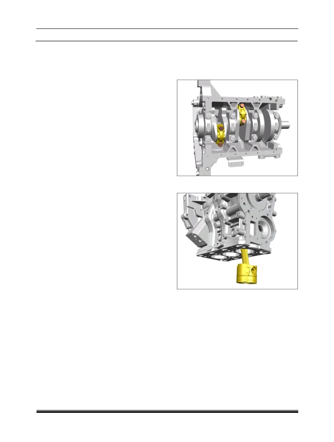
viii. REMOVAL OF CYLINDER BLOCK SUB-
ASSEMBLIES :
1.
Turn the Crankshaft and bring a pair of pistons
near BDC position. Unscrew connecting rod
bearing cap mounting nuts.
2.
Push the piston assemblies out of cylinders
using wooden handle of mallet.
3.
Remove connecting rod bearing shells and
duly mark them with paint on their back in case
these are to be reused.
4.
Verify serial numbers on connecting rod
bearing caps and connecting rods.
5.
Remove remaining pistons in a similar manner
Note:
It is essential to assemble connecting rod bearing
caps to their respective connecting rods only.


