
1.05L REVOTORQ ENGINE
86
The following components must not, under any
circumstances, be removed from the pump inlet
hydraulic connector; Hp outlet hydraulic con-
nector and fuel return connector.
Do not carry the pump using drive shaft.
Injector electronics are polarized. In case of in-
tervention or wiring harness, do not invert wires.
It is destructive for the piezo components.
Don’t drive the injectors if their body is not con-
nected to the battery ground. Injector body has
to be in contact with cylinder head.
Do not try to drive the injectors with anything but
the ECU.
Do not make a short circuit between grounds of
injectors. Injectors will remain open: broken en-
gine.
Do’s
Monitor battery voltage continuously – recharge
battery if voltage drops below 10 Volts
Drain water from Sedimenter / filter at regular
intervals
Fix the rubber cover to the ECU to prevent dust /
moisture entry inside ECU.
EMS W/H to be properly routed as specified us-
ing clamps / clips and brackets.
Do check for any faults /malfunctioning in the
system using diagnostics tool before cranking
the engine
(after any repair).
Do fix ECU connector branch properly while
transporting engine.
If engine does not start check the respective
fuses related to 1.05 CRAIL components.
When Injectors are replaced/Changed Injector IC
values must be loaded correctly as per cylinder
order.
Plug the port of Common rail system compo-
nents whenever any pipe connections are
removed.
If the fuel tank is dry
(no diesel)
fill diesel and
use priming pump to suck the diesel till fuel filter.
Tighten the mounting nuts / cap nuts etc. only to
the specified torque values.
Always remove the Injectors before dismantling
the cylinder head. This is to avoid damage to the
injector nozzle tips which protrude out of cylinder
head. In case of HP pump removal handle the
pump with proper care to avoid any damage to
inlet pipe, venturi and connectors.
Always use specified tightening torques, during
assembling of 1.05 CRAIL components.
Components :
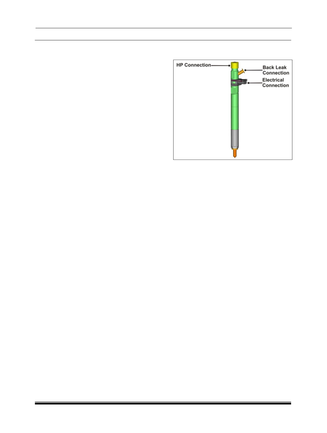
A. Injector :
The injector used in this engine is a piezo
injector. This is controlled by the EMS ECU. The
timing of injection and quantity is controlled by the
EMS ECU. It operates at a pressure of 1800 bar. It
makes multiple injections.
The piezo actuator is an electrically ener-
gized device that acts similar to a solenoid but is
much more precise. A piezo actuator is a composi-
tion of piezo discs, that when electrically energized,
cause the discs to deform resulting in an expansion.
This expansion results in a longitudinal motion thus
controlling the injector. When energized, the piezo
actuator pushes downward against the valve piston.
The piezo actuator is returned to its non energized
state via the ECU switching the polarity of the elec-
trical feed to the injector.


