


 457 / 801

BODY
13
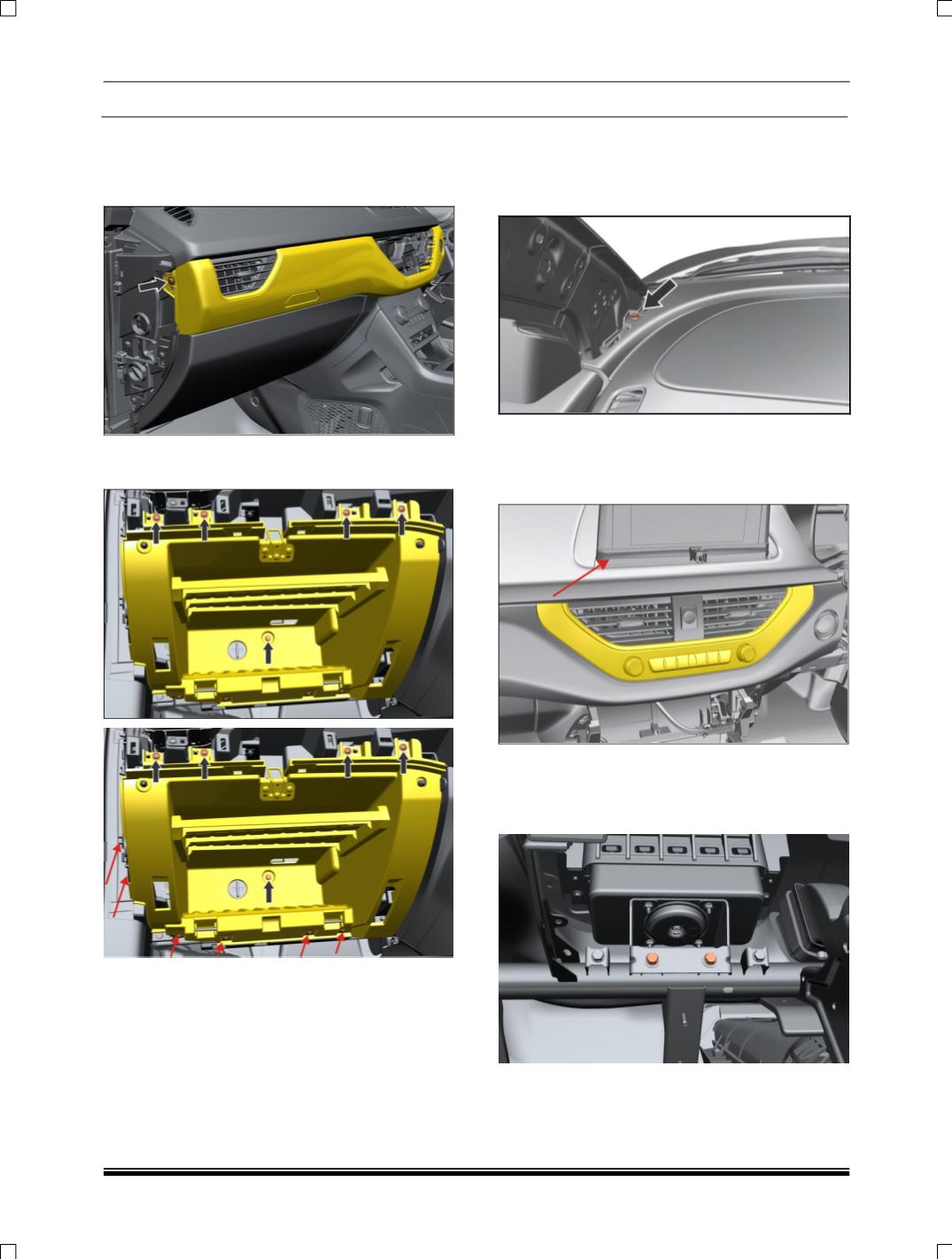
13. Remove electrical connections of Start stop
switch, remove two more screws at Glove Box
area of Mid Panel & Pull out dashboard mid
panel
.
14. Remove lower side & outboard side screws of
glow box assembly and pull out glove box
15. Remove PAB Assembly (If applicable). (For
procedure refer PAB removal process in SRS
section).
16. Remove ‘A’ pillar Lower trim. (For procedure
refer ‘A’ pillar trim removal process.)
17. Remove two mounting screw near A
pillar.(LH,RH)
18. Before removing mounting bolts of Dashboard
Panel need to Remove Display Bezels (Cap &
Lower Bezel) & 7” Display. Also disconnect
electrical connection of 7” Display unit
19. Before removing mounting bolts of Dashboard
Panel need to remove PAB Assembly after
removal of Glove Box assembly & disconnect
its electrical connection