


 848 / 1906

TRANSMISSION
33
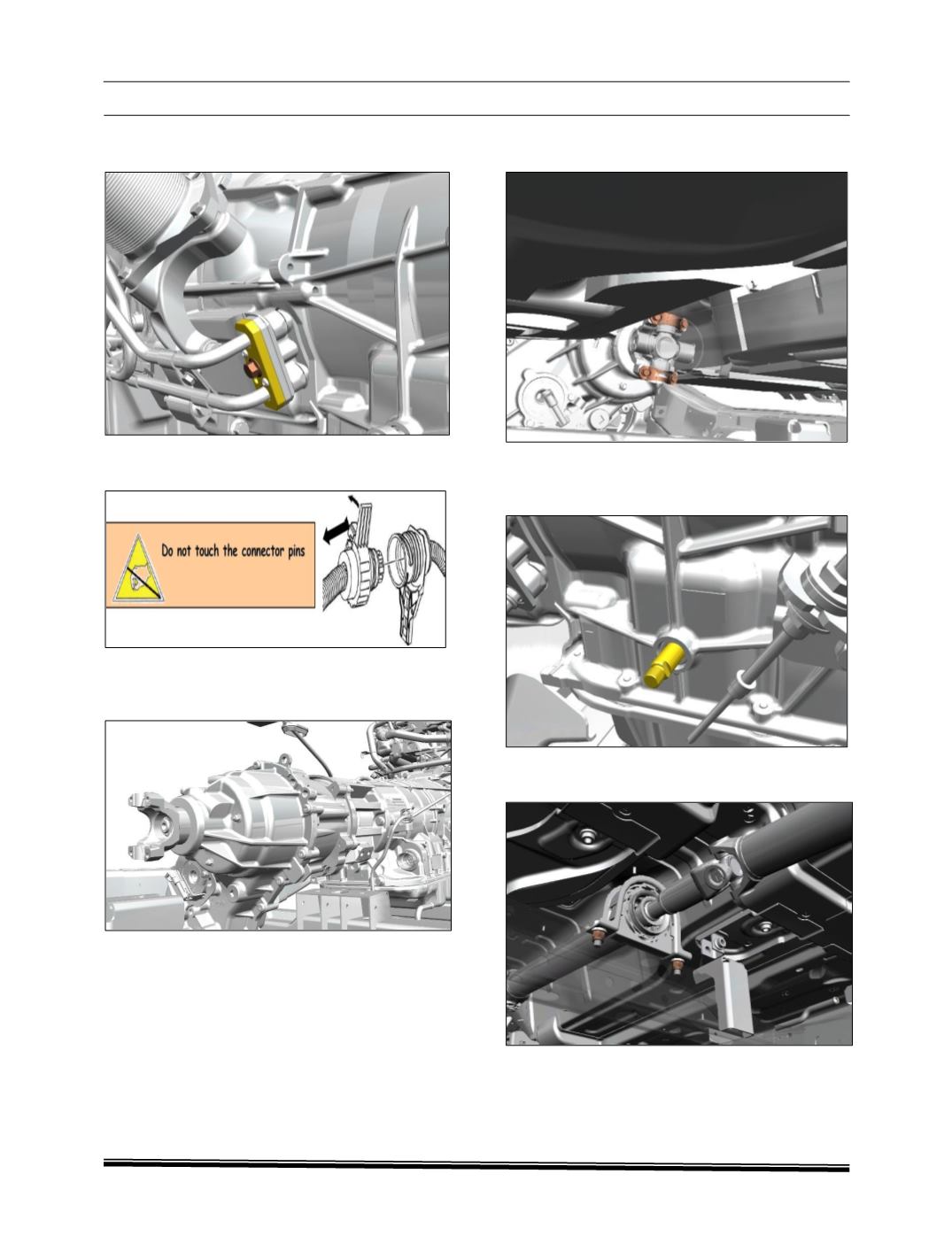
29. Install the cooler lines, and tighten the screw
to 2 to 2.5Kgfm.
30. Connect the vehicle connector. See
mechatronic removing Procedure.
31. Apply the 3GM of synthetic grease 365
SS6808
TS25205P1
–
Part
No.
55140860025.
32. Install the propeller shaft on drive flange.
33. Tighten the two drive flange screws to 6-
6.8kgm
tightening torque.
34. Using a H9 wrench, turn the selector shaft out
of park to allow propeller shaft turning and
access to the other drive flange screws.
35. Tighten the 2 support propeller shaft nuts to
8.6kgm tightening torque.