


 51 / 1526

22
4 DLT ENGINE
D
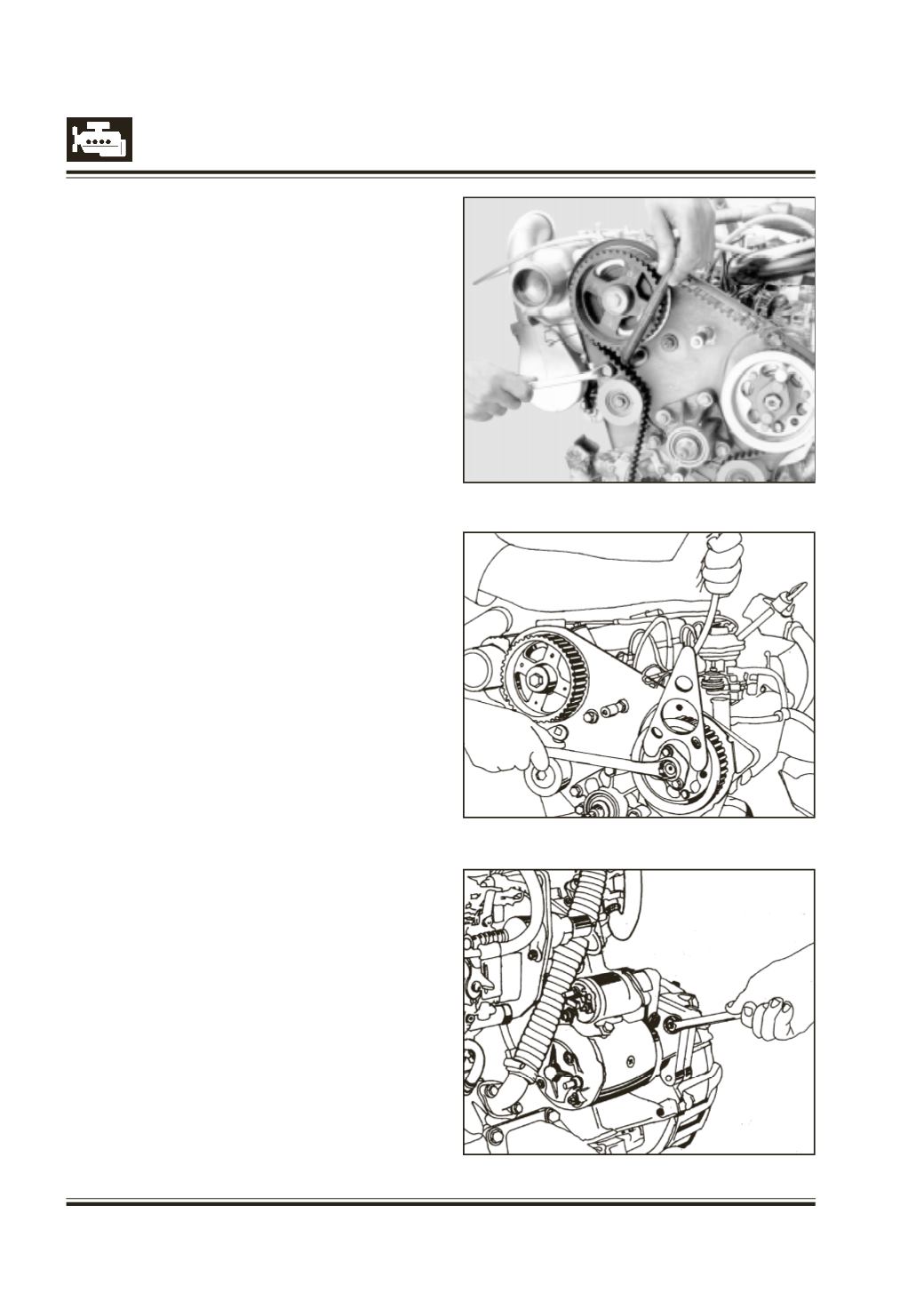
epress roller by using drive square pt. no. 2654 5890
05 10. Refer figure 24.
R
emove timing belt.
R
emove
-
O
verflow hose from 1st injector to fuel
injection pump.
-
C
oolant pipe.
-
H
igh pressure injection pipe from injectors to
fuel injection pump.
-
F
uel pipe from fuel filter to fuel injection
pump.
-
F
uel return pipe from fuel injection pump to
fuel tank.
-
F
ICD unit.
-
O
il separator and hoses.
- Thermostat assy. and Water Valve for cab heating
(if fitted).
D
isconnect engine stop solenoid and cold start unit
electrical cable from fuel injection pump.
H
old fuel injection pump gear with spanner, 2654 5890
05 01 and unscrew mounting nut to remove fuel
injection pump gear. Refer figure 25.
R
emove timing bolts and FIP gear.
R
emove woodruff key.
R
emove fuel injection pump rear mounting bolt and
taper nut, along with split sleeve.
U
nscrew and remove fuel injection pump front
mounting nuts.
R
emove fuel injection pump.
R
emove FIP mounting bracket.
R
emove starter motor assembly. Refer figure 26.
Fig. 24
Fig. 25
Fig. 26