


 54 / 1526

25
4 DLT ENGINE
U
nscrew and remove cylinder head mounting bolts in
reverse order of tightening. Refer figure 35.
S
lightly lift cylinder head to clear locating hollow dowel
in crankcase and remove it.
D
ismantling and assembly of the cylinder head is
explained separately.
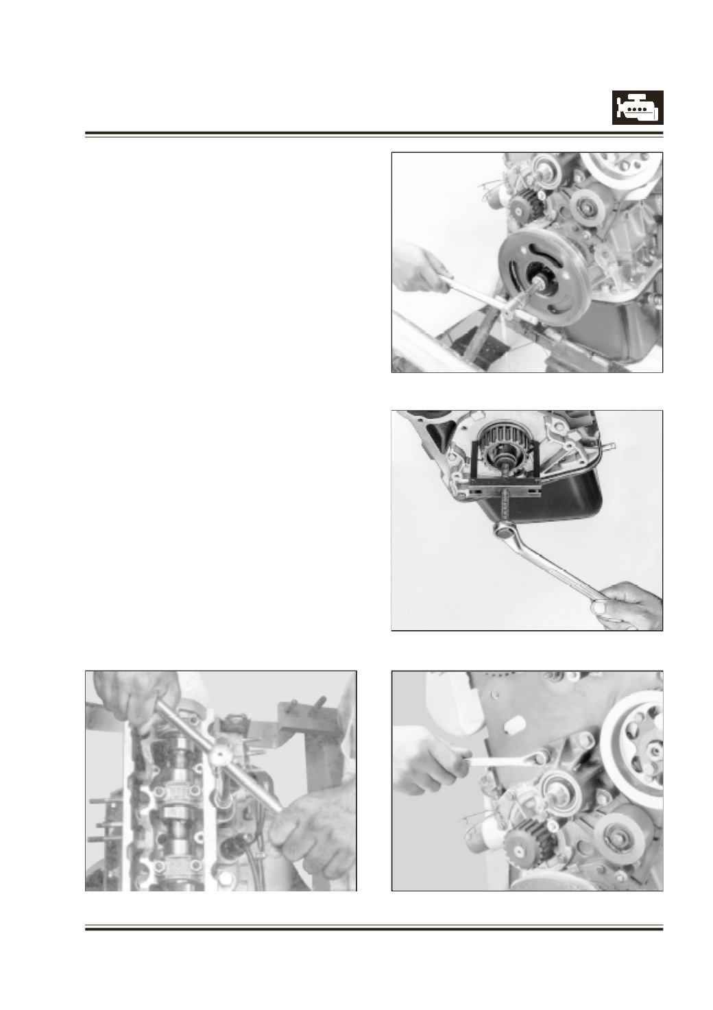
U
niformly and evenly unscrew clutch pressure plate
mounting screws and remove clutch pressure plate
and clutch disc.
L
ock flywheel suitably and unscrew crankshaft
pulley mounting bolt. Refer figure 36.
R
emove crankshaft pulley.
R
emove crankshaft gear using puller 2654 5890 03
05. Refer figure 37.
R
emove
- Tensioner roller.
- Fan mounting bearing block. Refer figure 38.
- Idler roller.
- Timing gear train rear cover.
Fig. 36
Fig. 37
Fig. 38
Fig. 35