


 402 / 1526

26
FRONT AXLE - 4
X
4
Align holes of the gears up with case and assemble
shaft.
Fig. 39
DRIFT
DIFFERENTIAL
PINION SHAFT
PEEN METAL
OF CASE
Fig. 39
Fig. 40
Fig. 41
Ensure that vertical lock pin hole is lined up with
that of the case, and that pinion mate washers are
in place and lined up with gear and case.
Assemble roll pin.
Fig. 40
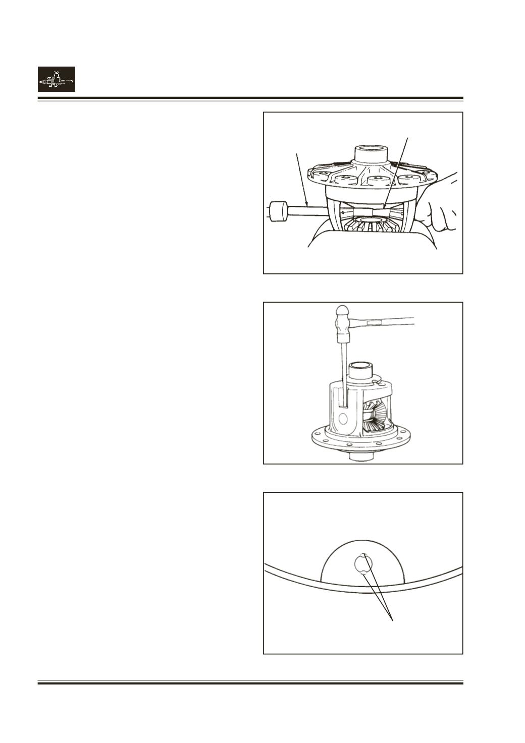
Stake (peen) metal of case over pin at two places.
180
0
apart to ensure the position of differential pinion
shaft.
Fig. 41