


 403 / 1526

27
FRONT AXLE - 4
X
4
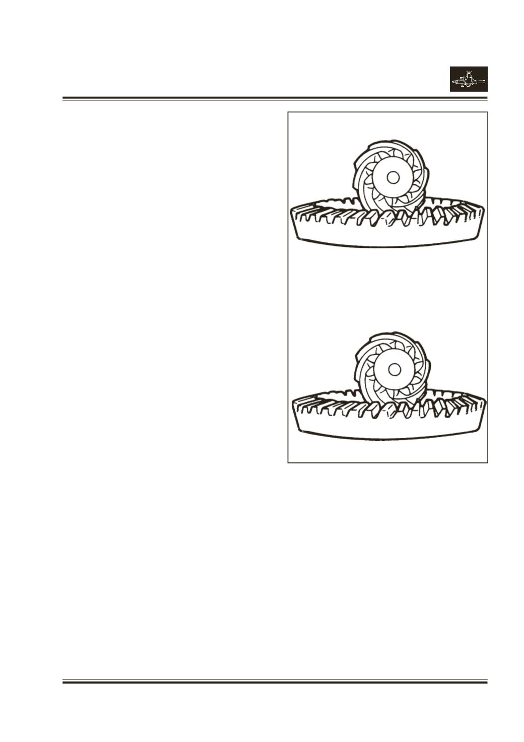
RING AND PINION GEAR ASSEMBLY THEORY
Ring gear and pinions are supplied in matched sets
only. Matching numbers on both pinion and ring gear
are etched for verification.
Fig. 42
If a new gear set is being used, verify the numbers of
each pinion and ring before proceeding with assembly.
The mounting distance from the center line of the ring
gear to the back face of the pinion for the front axle is
3.625 Inch. (92.08 mm.)
On the bottom end of each pinion, there is etched a
plus (+) number, a minus (-) number, or a Zero (0)
number, which indicates the best running position for
each particular gear set. This dimension is controlled
by selecting shims, between the inner pinion bearing
cone and pinion gear.
For example : If a pinion is etched +3 (m+8), it would
require 0.003 in. (0.08 mm) less shim than a pinion
etched ‘O’. This means decreasing shim thickness;
increase the mounting distance of the pinion to 3.625
in. (92.15 mm). If a pinion is etched -3 (m-8) it would
require adding .003 in. (.08 mm) more to the shim
than would be required if the pinion were etched ‘O’.
By adding .003 in. (.08 mm), the mounting distance of
the pinion was decreased to 3.622 in. (91.9mm) which
is just what a -3 (m-8) etching indicated.
To change the pinion adjustment, use different shims
which come in different thicknesses.
Use the tables on next page as a guide for selecting
the correct number of shims to add or subtract from
the old shim pack.
A
B
F
+3
0
750
+8
750
Fig. 42
Fig. 42 A shows ring and pinion etched with inch
identification. Refer Table A.
Fig. 42 B shows ring and pinion etched with metric
indentification. Refer Table B.
k
200
200
m
o