


 408 / 1526

32
FRONT AXLE - 4
X
4
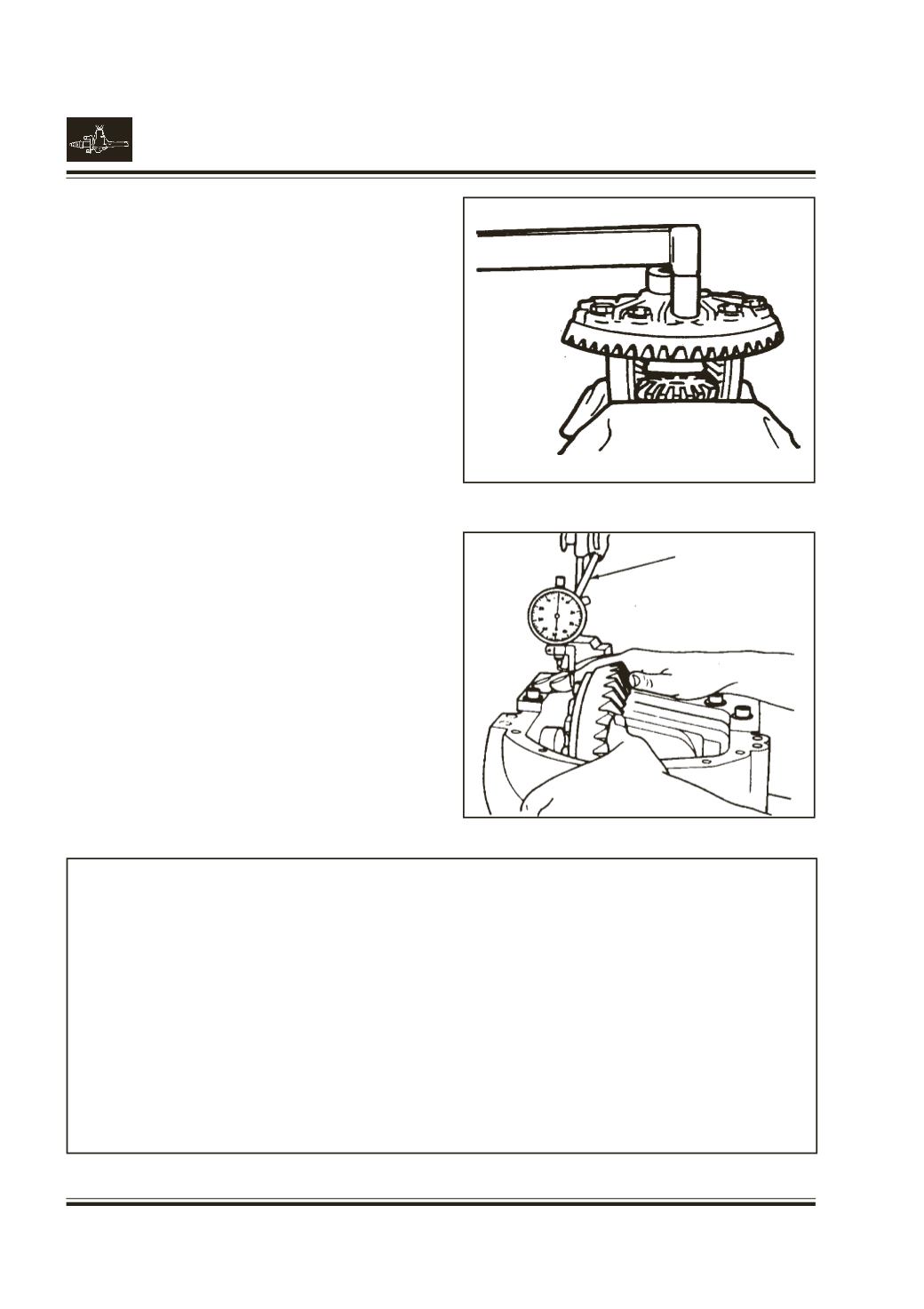
Remove indicator and differential assembly from
housing.
Remove master bearings from hubs and set aside.
Assemble ring gear to case.
Fig. 53
Note :
Use new ring gear screws.
Draw up screws alternately and evenly. Torque ring
gear screws to specification.
Assemble master differential bearing onto case hubs.
Place differential assembly into housing. Set up dial
indicator and locate lip of indicator on flat surface of
one of the ring gear screws.
Force the differential case assembly (with ring gear)
away from the pinion gear. With force still applied to
the differential case, set indicator at (0) zero.
Fig. 54
Now push the differential case assembly to the other
side.
Force the differential case assembly and ring gear
to mesh with the pinion gear. Rock ring gear to allow
the teeth of the gear to mesh. Take reading.
Repeat until the same reading is obtained.
Record this as measurement
B
Remove master bearings.
GEAR BACKLASH AND DIFFERENTIAL
DIAL
INDICATOR
Fig. 53
Fig. 54
WORKSHEET FOR CALCULATING RING GEAR
BACKLASH AND DIFFERENTIAL BEARING
PRELOAD SHIMS.
1.Total amount of space
Measurement
A
______
measured without ring gear.
2.Total amount of space
Measurement
B
______
measured with gear set assembled in carrier.
3.Measurement A minus
Measurement
C
______
Measurement B equals calculated.
Assemble the shim pack using the figure determined in A,B,&C adjusting the packs as described below.
RING GEAR SIDE :
Assemble shim pack to measurement
B
- 0.125 mm. or B - 0.005"
OPPOSITE SIDE OF RING GEAR :
Assemble shim pack to measurement
C
. Add 0.20 mm or 0.008" for differential bearing preload and backlash.