
ELECTRICAL
42
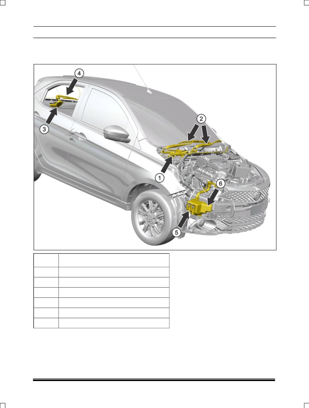
8.9.1 FRONT AND REAR WIPER AND WAHSER SYSTEM LAYOUT
The illustration below locates and identifies the main components in the wiper and washer system, which is
operated by LH side stalk of a combi-switch.
SR. NO. DESCRIPTION
01
FRONT WIPER MOTOR
02
FRONT WIPERS
03
REAR WIPER MOTOR
04
REAR WIPER
05
WASHER PUMP
06
WASHER BOTTLE


