
BRAKES
34
FRONT BRAKE ASSEMBLY
Ventilated disc brakes with single pot caliper of 54
mm piston diameter are provided for front brake.
Salient features of disc brakes
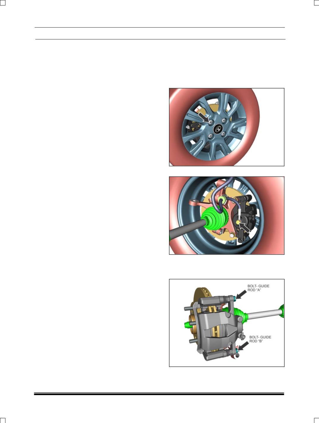
Caliper assembly consists of a caliper carrier
bolted to the knuckle and the body assembly
slides on two guide rod pins used in the carrier
(guide rod ‘A’ & ‘B’). Both the sliding guide rod
pins are sealed against water and dust by boot
guide rod thereby avoiding possible unequal
sliding loads caused by dirt, corrosion. Drag of the
pads is taken directly by the carrier; consequently
the pins are loaded only by the weight of the
caliper body.
When the brake pedal is pressed, the hydraulic
pressure from Master Cylinder pushes the piston
in the caliper pot and with it the in-board pad on to
the disc. The caliper body reacts and slides on the
guide rod pins to bring the out-board pad into
contact with the disc. Thus the clamping forces on
both sides of the disc become equal.
When the hydraulic pressure is released, upon
release of the brake pedal the sealing ring fitted in
the groove of the caliper pot retracts the piston by
a small amount which allows the moving parts to
relax sufficiently for the disc pads to retract and
remain in close proximity to disc, ready for the
next brake application.
6.13.1
FRONT
BRAKE
ADJUSTMENT,
REMOVAL AND REFITMENT
REMOVAL OF CALIPER FROM CARRIER
1. Use a socket and wrench/Pneumatic nut
runner to remove the wheel from the axle. Do
opposite (or diagonal) loosening of nuts
carefully.
2. Remove Banjo bolt from inlet port.
3. Loosen and remove the Bolt- guide rod ‘A’ and
Bolt- guide rod ‘B’ from carrier and remove the
caliper from the carrier


