
DRIVETRAIN-TA65 Star
62
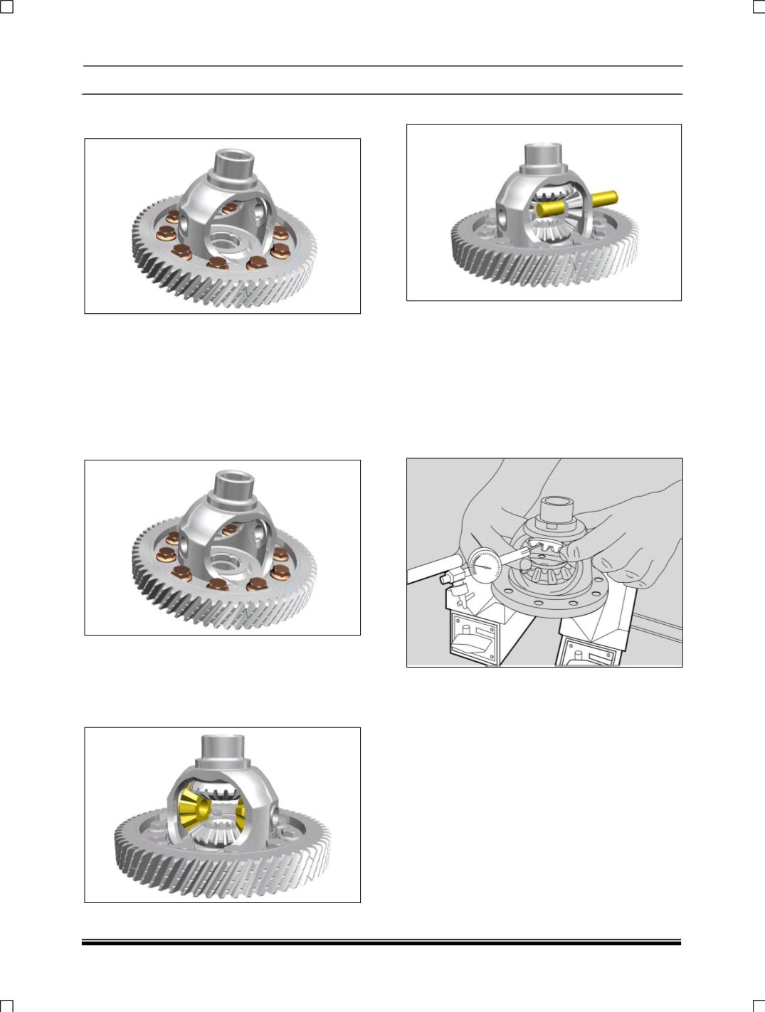
9. Unscrew and remove the collared bolts (10
Nos.).
2. ASSEMBLY:
1. Hold fixture for gear on differential casing on
soft jaw vice.
2. Mount differential housing on fixture part no.
2702 5890 2609 and lock it.
3. Place gear final drive on differential housing.
Tighten the collared bolts (10 nos.) to
specified torque of 8 to 9 mkg.
4. Place both the bevel gear on the differential
housing with spacer.
5. Place another set of idler bevel gear on the
already lifted bevel and rotate by 90° so as to
align the bevel to spider shaft hole.
6. Push the spider into the hole.
7. Check the free play of differential gears. It
should be 0-0.1 mm.
8. If the value of play is not within specifications,
then try with different thickness washer.
9. Assemble the two 15x1.5 thick circlips into the
groove near the ends of spider.
To check backlash, hold the two different
pinions and one side gear and check free play
or remaining side gear teeth flank as shown in


