
DRIVETRAIN-TA65 Star
61
4.7. Q. DIFFERENTIAL ASSEMBLIES:
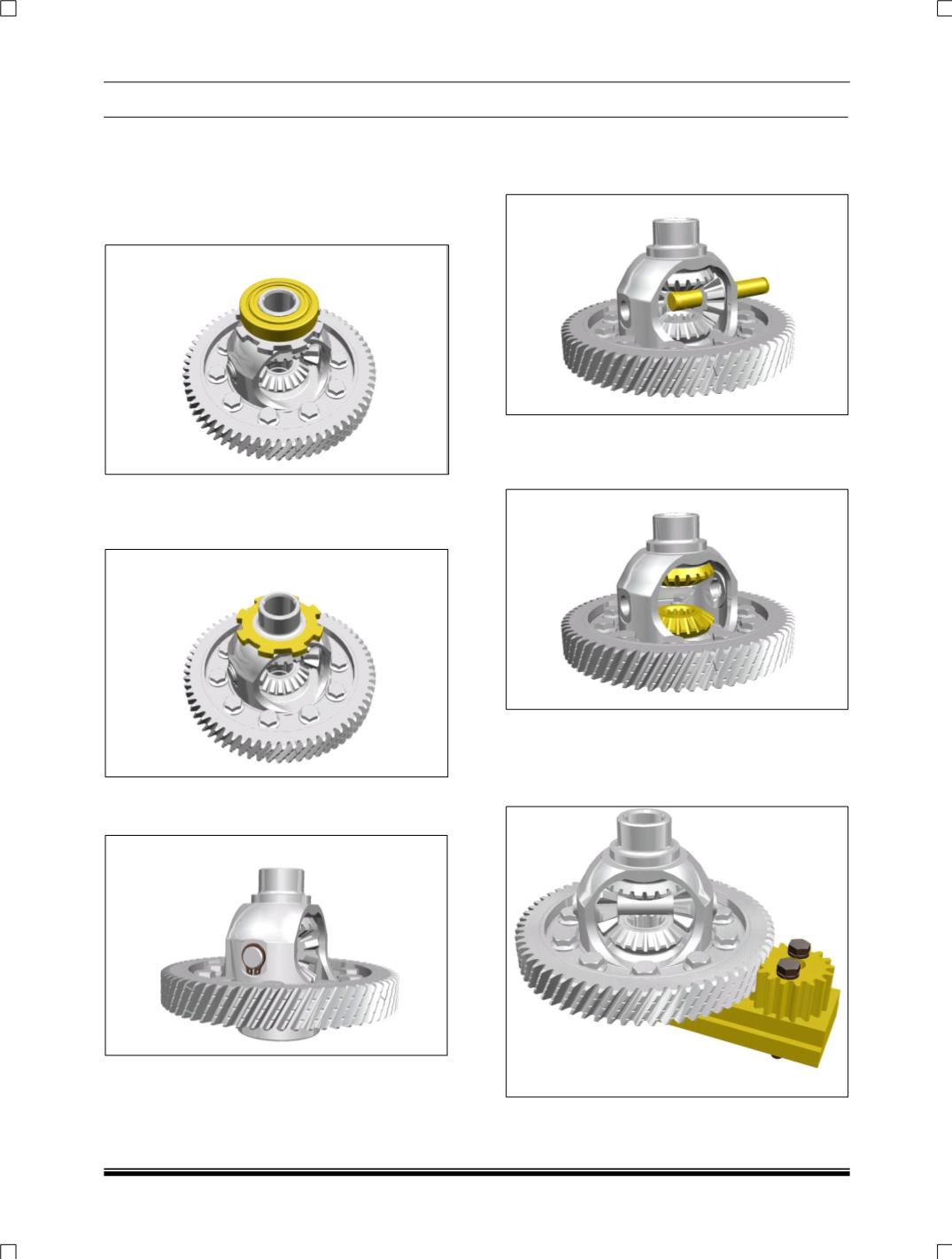
1. DISASSEMBLY:
1. Remove taper roller bearings by using puller
part no. 2702 5890 2604, and rest pad part
no. 2702 5890 2612N.
2. Remove sensing wheel using by puller part
no. 2651 5890 3506 and rest pad part no.
2702 58902612N.
3. Remove two (1.5 Thick) circlips locking the
spider.
NOTE:
DO NOT REUSE THE 1.5 THICK CIRCLIPS.
4. Push out spider from differential housing.
5. Rotate bevel pinions by 90
0
and remove the
side bevel gears.
6. Remove bevel pinions with washers.
7. Hold fixtures for gear on differential assembly
part no. 2702 5890 2609 in soft jaw vice.
8. Mount differential housing on fixture part no.
2702 5890 2609 and lock it.


