


 153 / 310

ENGINE
107
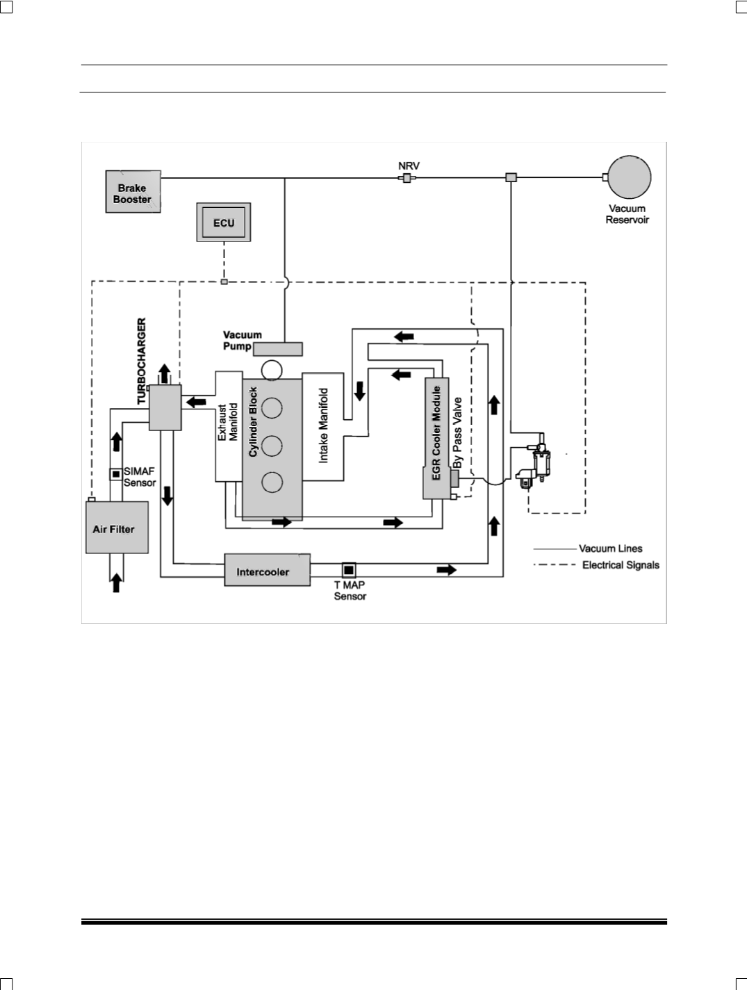
2.1.4.6 VACUUM MANAGEMENT SYSTEM
2.1.4.6.1 VACUUM LINES SCHEMATIC LAYOUT
The above schematic shows the vacuum circuit. A
vacuum pump provides vacuum to the vacuum sole-
noid valve and the brake booster.
The vacuum generated by the vacuum pump is
stored in the vacuum reservoir.
The vacuum circuit of Brake booster and vacuum
solenoid valve are separated by a Non return valve.
The NRV and vacuum reservoir is provided so that
there is no vacuum starvation by EGR cooler bypass
valve irrespective of braking applications. The vacu-
um reservoir is mounted to fire wall with the help of a
bracket.