


 997 / 1904

TRANSAXLE-AMT
47
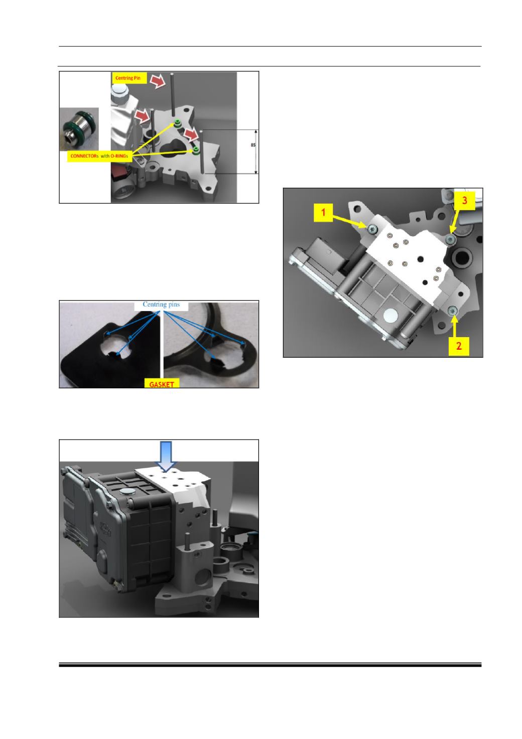
5. Lubricate with new ‘CS Speed’ oil the
‘Mechatronic Gear Actuator’ seats for
connectors with O-rings.
6. Assemble the spare part gasket on the spare
part ‘Mechatronic Gear Actuator’ with the
correct orientation, inserting the centering pins
into the fixing holes of the ‘Mechatronic Gear
Actuator’ body.
7. Position the ‘Mechatronic Gear Actuator’ with
gasket over the ‘Power Unit Base Plate’, using
for reference the threaded rods and moving it
parallel towards the mating surface.
8. When the ‘Mechatronic Gear Actuator’ body
seats come in contact with O-rings push it
slowly with appropriate load to complete the
assembly.
9. Unscrew the rods and screw without tighten
the three spare parts screws for fixing the
‘Mechatronic Gear Actuator’ on ‘Power Unit
Base Plate’.
10. Tighten screw at the right torque 10 ± 1 Nm,
following the order shown in the image below.
11. Connect the connector of the wiring harness
on the ‘Transmission Control Unit’.
12. Fill the ‘Oil Tank’
with new ‘CS Speed’ oil, up
to the Max. Level ‘@ 0 bar’ (no pressure in the
hydraulic circuit) and restore it after the purge
procedure. Screw the ‘Oil Tank Cap’
at the
right torque 2 - 0.5 ± 1 Nm.