


 996 / 1904

TRANSAXLE-AMT
46
7.0 MECHATRONIC GEAR ACTUATOR
UNIT (MGA) REMOVAL AND RE-FITMENT
ON BENCH:-
Removal:
CAUTION
Ensure there is ‘NO PRESSURE’ in the
hydraulic circuit.
1. Disconnect the connector of the wiring harness
from the ‘Transmission Control Unit’.
2. Drain the hydraulic oil from the ‘Oil Tank’, by
first unscrewing the ‘Oil Tank Cap’ and then
remove hydraulic system and drain oil in to
canister.
3. Unscrew and remove the three screws fixing
‘Mechatronic Gear Actuator’ on ‘Power Unit
Base Plate’.
4. Remove the ‘Mechatronic Gear Actuator’ by
pulling its body by hand in vertical direction;
pay attention that a small quantity of oil will
flow out from the tank port.
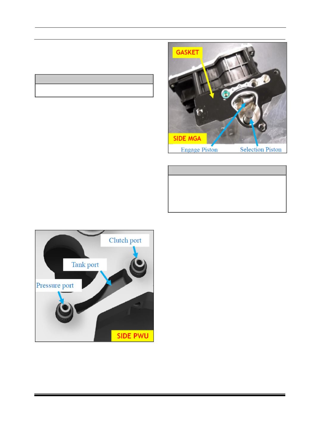
5. Remove the oil port’s connectors with O-rings
and the flat gasket. In the pictures below is an
example of dismounting, where the gasket and
one O-ring remain in the ‘Mechatronic Gear
Actuator’ seat and the other parts remain in the
‘Power Unit Base Plate’ Seats.
Installation:
NOTE
Verify that the gearbox is in neutral gear
position, because the ‘Mechatronic Gear
Actuator’ spare part is provided in this position,
otherwise rotate the gearbox command lever by
hand to achieve the position corresponding to
the spare part before mounting.
1. In order to guarantee right ‘Mechatronic Gear
Actuator’ translation during the mounting, to
avoid O-rings damages, screw three rods
φ6x100 mm length, with 15 mm threaded M6,
in the ‘Power Unit Base Plate’ holes used by
right ‘Mechatronic Gear Actuator’ fixing screws
and shown in the picture below.
2. Remove traces of oil from the ‘Power Unit
Base Plate’ seal surface in contact with the
spare gasket, with care to avoid contamination
from foreign materials (dust, metal burrs,
etc…) or surface damages.
3. Assemble the spare parts O-rings on the spare
parts connectors (see the detail on below
picture).
4. Mount the spare parts connectors with O-rings
in their ‘Power Unit Base Plate’ seats (see
picture below), after lubrication with new ‘CS
Speed’ oil.