


 55 / 801

HV ELECTRICAL SYSTEM
47
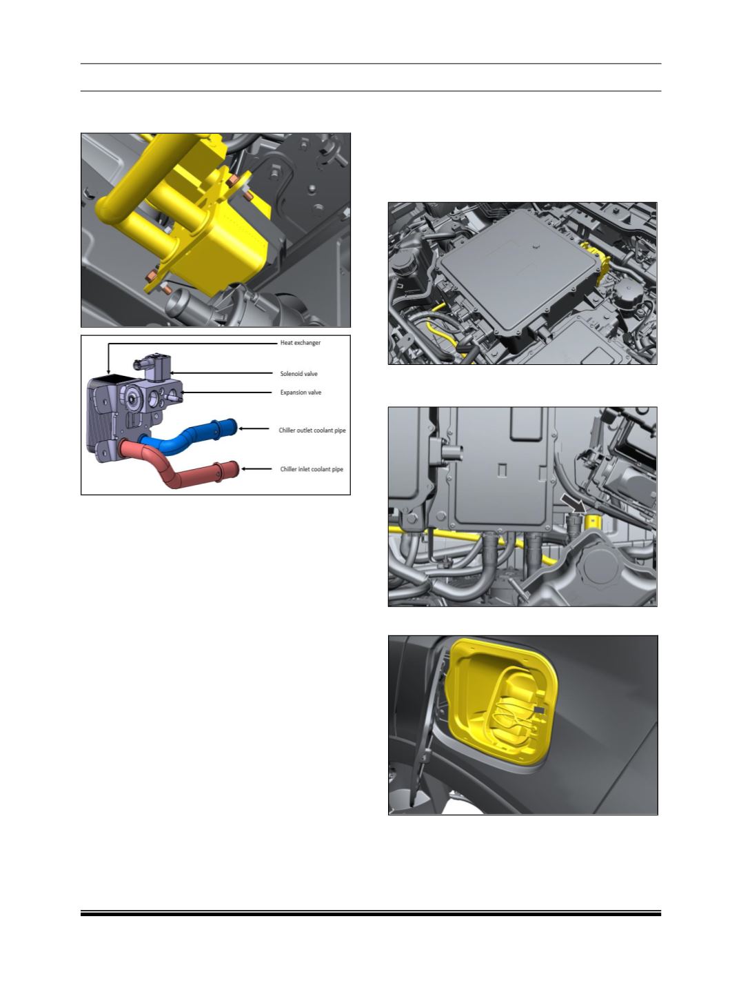
8. Remove the mounting screw of heat
exchanger of bracket.
Fitment
Follow reverse procedure for assembly.
Tighten the following fasteners to the
recommended torque.
i) Compressor mounting.
ii) Refrigerant lines on compressor.
•
Service and Maintenance
Coolant drain and refill
• Conduct activity when BCS pump is off
• Remove cap of auxiliary tank
• Remove one connection from battery inlet /
outlet joint and drain the coolant.
Refilling of coolant
• Close all joints
• Fill coolant from auxiliary tank
• Follow de-aeration process.
I. HV / LV CHARGER PORT & CABLE
REMOVAL
1. Refer Instructions for working on HV
Components mention before starting work.
2. Remove the connector and cable of HV
charger to vehicle inlet connection connected
to PDU.
3. Disconnect the cable connectors connected to
the charger to vehicle inlet connection.
4. Pull out the fuel cap outside.