


 102 / 745

KRYOTEC ENGINE
94
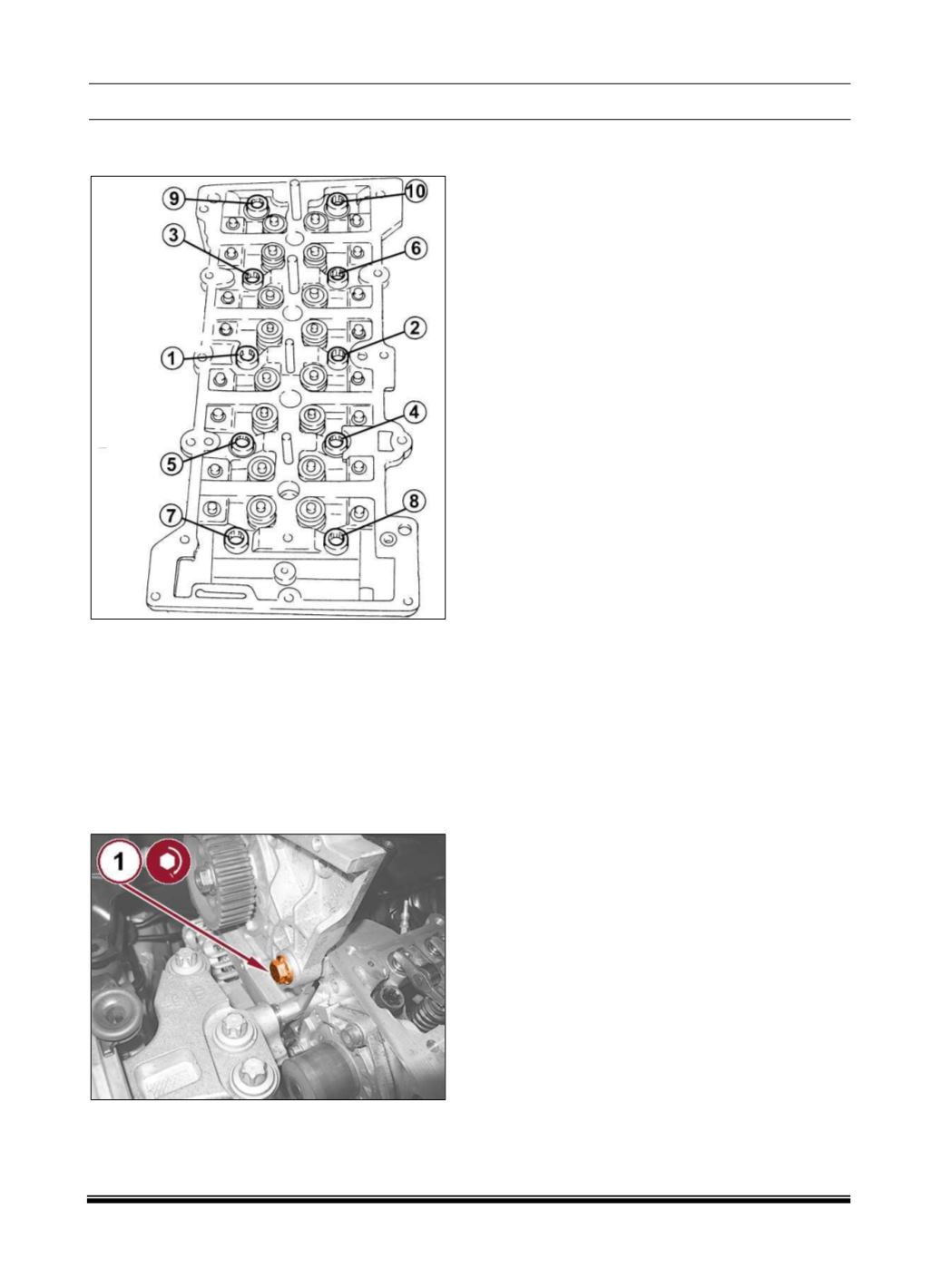
7. In the order shown, tighten the cylinder head
bolts to the proper (Torque Specifications).
NOTE
The value of 65 N•m (48 ft. lbs.) must be done with
a combination of 20 N•m (15 ft. lbs.) and
subsequently an increase of 45 N•m (33 ft. lbs.).
8. Install the hydraulic lifters in their bores complete
with rockers.
9. Install the fuel injection pump support to the
cylinder head and tighten the bolt (1) to the proper
(Torque Specifications).
10. Install the dipstick tube to the engine and
securely tighten the bolt.
11. Install the radiator hose and securely tighten
the clamp.
12. Install the hose onto the oil vapor separator and
securely tighten the clamp.
13. Install the upper bolt securing the oil vapor
separator and securely tighten.
14. Connect the coolant return manifold quick
connect coupling.
15. Position the wire harness and install the front
screw.
16. Connect the boost pressure sensor wire
harness connector.
17. Connect the glow plugs wire harness
connectors.
18. Install the cylinder head cover (Refer to 09 -
Engine/Cylinder
Head/COVER(S),
Cylinder
Head/Removal and Installation).
19. Install the EGR cooler (Refer to 25 - Emissions
Control/Exhaust
Gas
Recirculation,
Diesel/COOLER, Exhaust Gas Recirculation
(EGR)/Removal and Installation).
20. Install the battery tray (Refer to 08 -
Electrical/Battery System/TRAY, Battery/Removal
and Installation).
21. Install the engine cover (Refer to 09 -
Engine/COVER, Engine/Removal and Installation).