


 578 / 1232

Automated Manual Transmission
50
Clutch Control Solenoid Removal
1.
Place the car on a lift.
2.
Position the gear lever at N.
3.
Connect the diagnosis equipment and car-
ry out the accumulator depressurization
procedure.
4.
Remove protection/guard under engine.
5.
Remove battery.
6.
Remove battery support/drip tray.
7.
Remove wiring for manual gearbox hy-
draulic selection system on hydraulic
selection unit
8.
Remove hydraulic speed selection hydrau-
lic actuator unit and clutch.
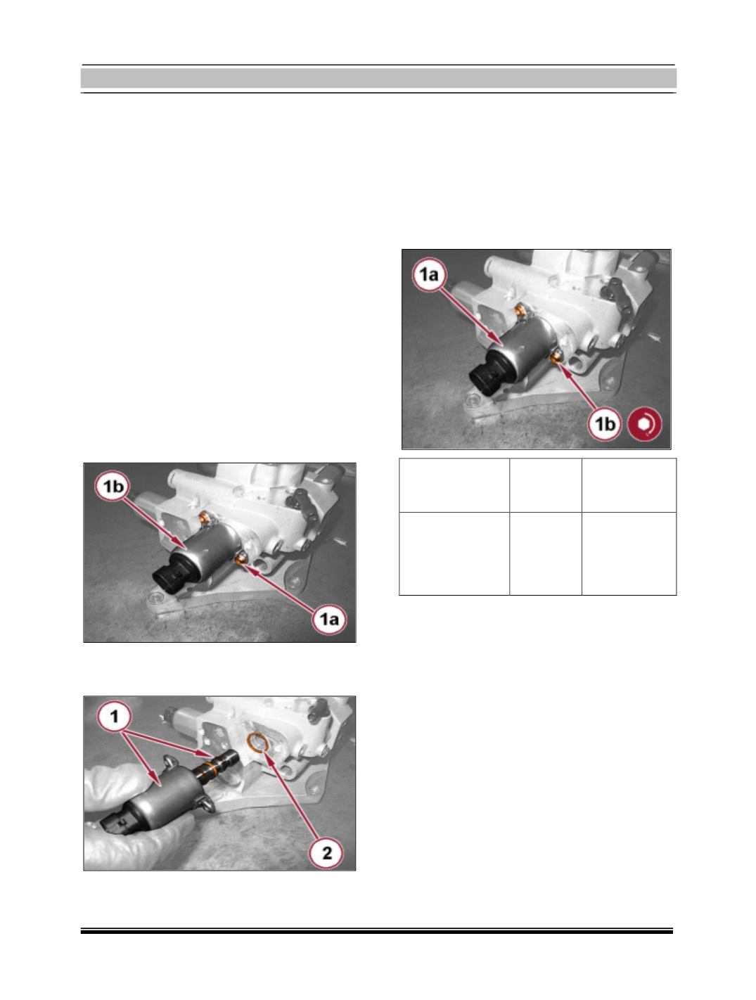
9.
Loosen and remove the screws (1a) for the
clutch control solenoid valve (1b).
10. Remove the clutch control solenoid valve
complete with O-rings.
11. Remove the O-ring from the clutch con-
trol solenoid valve seat.
Clutch Control Solenoid Fitment
1.
Fit a new O-ring in the clutch control sole-
noid valve seat.
2.
Place the clutch control solenoid valve (1a)
in its seat complete with new O-rings and
tighten the screws (1b) to the prescribed
torque.
Component
Fixing
value
(Nm)
Clutch control
solenoid valve
Screw
3 – 4.2
3.
Fit hydraulic speed selection hydraulic ac-
tuator unit and clutch
4.
Fit wiring for manual gearbox hydraulic
selection system on hydraulic selection
unit
5.
Fit protection/guard under engine.
6.
Refill the electro-hydraulic selection gear-
box hydraulic control system, with
reference to
7.
Check level of hydraulic system fluid for
gearbox with hydraulic selection and top
up, if necessary.
8.
Fit battery support/drip tray.
9.
Fit battery.
10. Connect the diagnosis equipment and