


 651 / 1265

TA6300 AMT KIT
12
INSTALLATION:
NOTE
After ‘Transmission Control Unit’ dismounting the
relevant screws must be discarded too.
Verify that the electro valves, pressure sensor and
ground tab connections does not show any visible
anomalies in displacement or damaging.
Verify the right cleanliness of the electro valve
block on the ‘Transmission Control Unit’ mating
side. No contamination from foreign materials is
acceptable (oil, dust, metal burrs, etc.). If
necessary, cleaning process must be previously
approved by ‘MAGNETI MARELLI’.
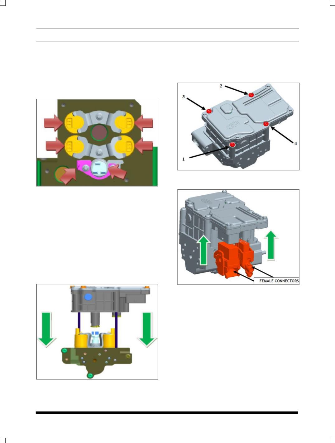
Position the ‘Transmission Control Unit’ over the
electro valve block, still using for reference the
two threaded rods and moving it parallel towards
the mating surface. Insertion of all the electro
valves, pressure sensor and ground tabs must be
obtained by appropriate load on the ‘Transmission
Control Unit’ heat sink and following handling
precautions.
Once the ‘Transmission Control Unit’ is positioned
mated to the electro valve block, remove the two
threaded rods.
Insert the new four ‘Transmission Control Unit’
fixing screws into the corresponding holes and
tighten each screw by applying a torque of 6.0 ±
1.2 Nm, following the order shown in the image
below. Please consider that screw on pos. 1 is M5
x 55and screws on pos. 2, 3 and 4 are M5 x 68.
Engage the two female connectors with the cable
on the ‘Transmission Control Unit’.
OIL TANK REMOVAL AND REFITMENT ON
BENCH:-
CAUTION
Ensure there is “NO PRESSURE” in the hydraulic
circuit.
Removal:
Unscrew the ‘Oil Tank Cap’ and empty the
hydraulic oil from the ‘Oil Tank’ in a canister.
Unscrew and remove the three screws M6x15
fixing ‘Oil Tank’ on ‘Power Unit Base Plate’ body.
Unscrew and remove the other screws M6x20
located under the ‘Power Unit Base Plate’ body.
With the Hydraulic System upright to avoid oil
draining from e ‘Power Unit Base Plate’, remove
the ‘Oil Tank’ pulling by hand in vertical direction.