


 654 / 1265

TA6300 AMT KIT
15
10 CLUTCH POSITION SENSOR REMOVAL
AND RE-FITMENT ON BENCH:-
Removal:
1. Disconnect the connector of the wiring
harness from the ‘Clutch Position Sensor’.
2. Unscrew and remove the two screws fixing
the ‘Clutch Position Sensor’ on the ‘Power
Unit Base Plate’ body.
Installation:
1. Position the spare part ‘Clutch Position
Sensor’ on its seat using the two spare parts
screws of fixing for reference.
2. Screw the two spare parts screws at the right
torque 2.5 ± 0.1 Nm.
3. Connect the connector of the wiring harness
on the ‘Clutch Position Sensor’.
11
HYDRAULIC
OIL
ACCUMLATOR
REMOVAL AND RE-FITMENT ON BENCH:-
DANGER!!
Do not remove hydraulic oil accumulator, it is
pressurized unit it can pose a safety threat.
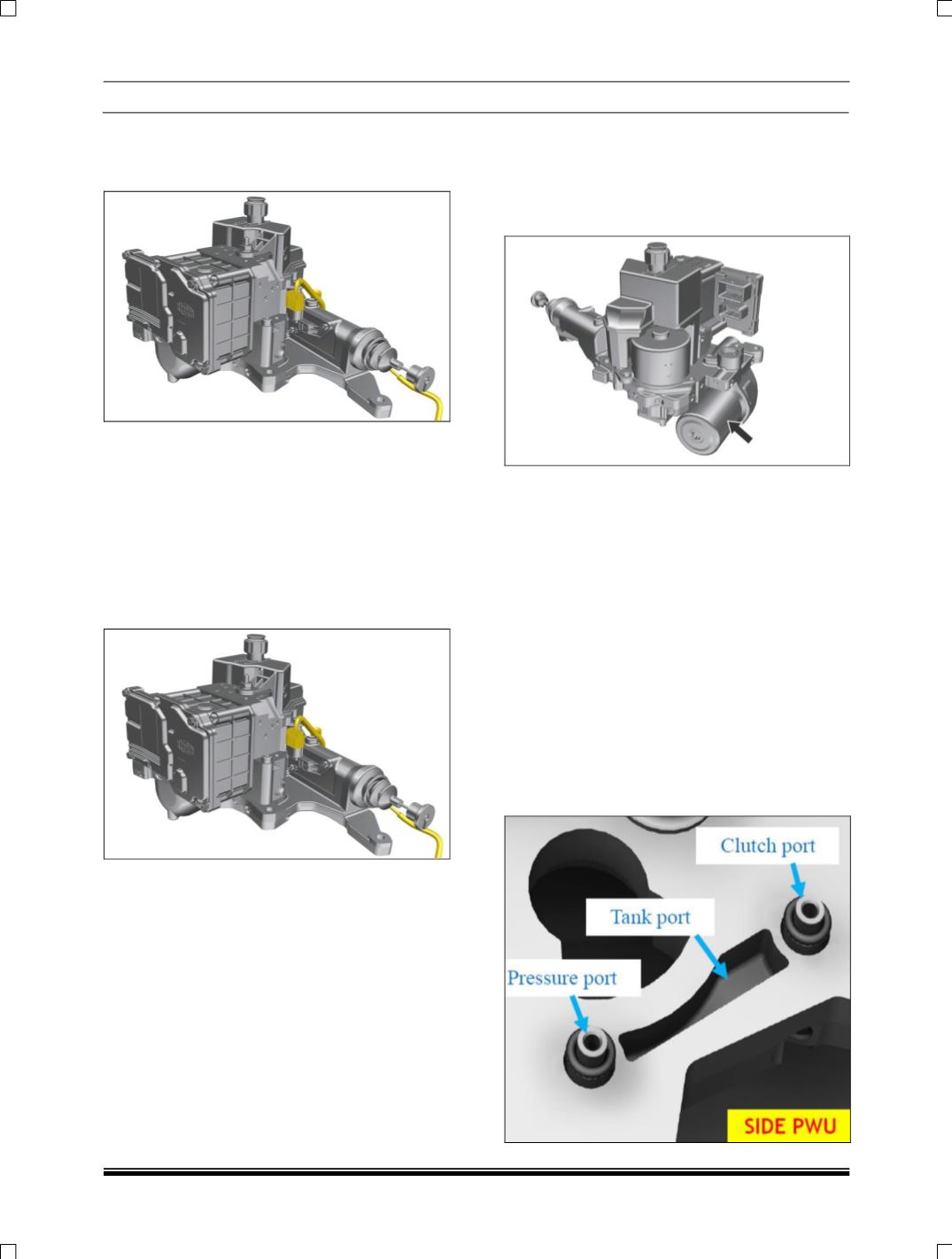
12 POWER UNIT (PWU) BASE PLATE
REMOVAL AND RE-FITMENT ON BENCH:-
Removal:
CAUTION
Ensure there is “NO PRESSURE” in the hydraulic
circuit.
1. Disconnect all the connectors of the system
wiring harness (DC Motor, Cultch Position
Sensor and Transmission Control Unit) and
remove the ‘Plastic Clip’ pulling it out from its
threaded hole on the ‘Power Unit Base Plate’
body.
2. Remove the ‘Mechatronic Gear Actuator’ unit
(MGA) first (refer the procedure 7.
Mechatronic Gear Actuator Unit (MGA)
Removal and Re-Fitment on Bench).