


 1383 / 1906

ELECTRICAL
81
8.8
WIPER and WASHER SYSTEM
8.8.1 FRONT AND REAR WIPER AND WASHER SYSTEM COMPONENT LOCATIONS
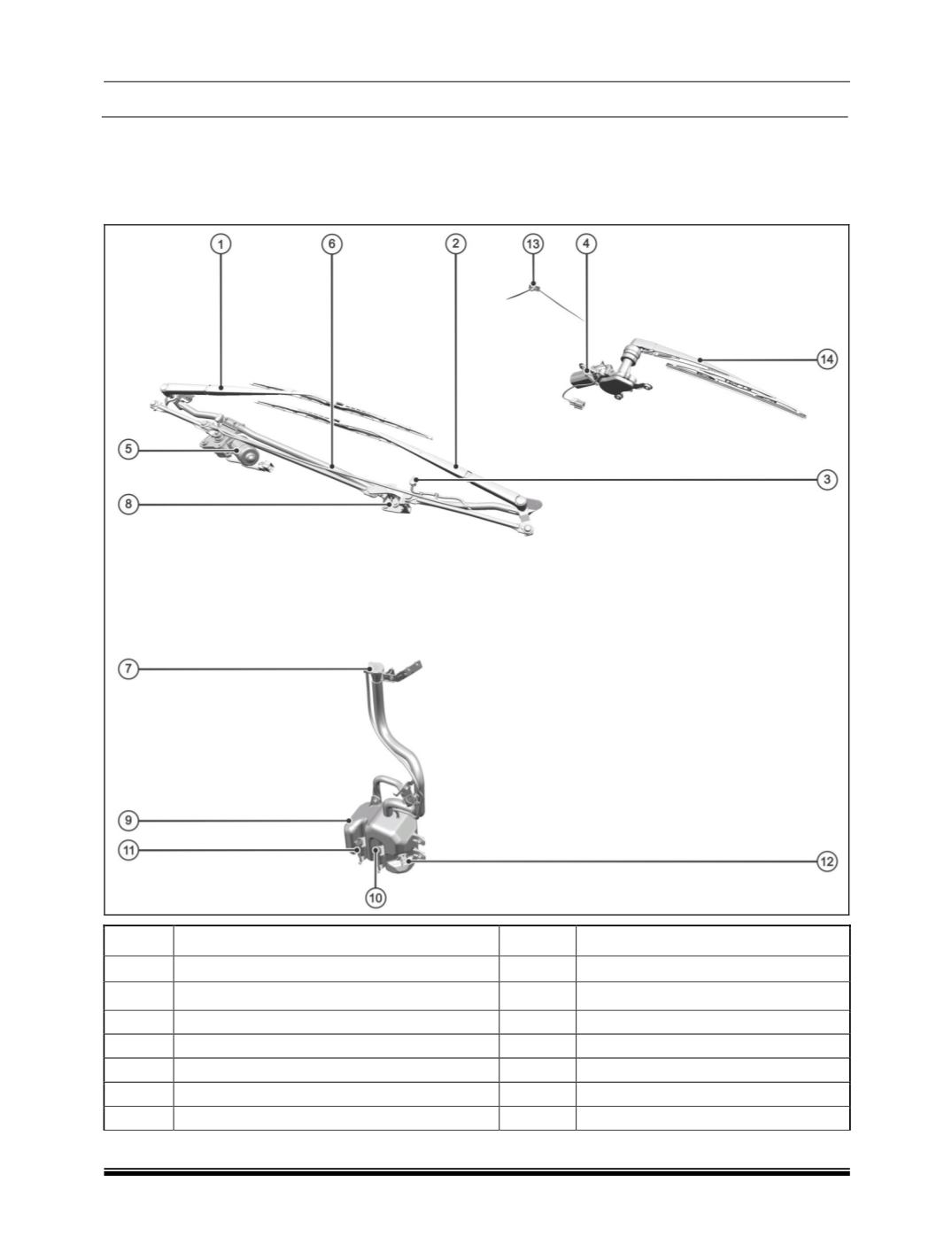
The illustration below locates and identifies the main components in the wiper and washer system, which is
operated by LH side stalk of a combi-switch.
Sr. No.
DESCRIPTION
Sr. No.
DESCRIPTION
01
Front Wiper Arm and Blade Driver Side.
08
Front wiper linkages
02
Front Wiper Arm And Blade Co-Driver Side.
09
Washer Bottle 3.0 Lit
03
Front Nozzle
10
Pump Assy (
Rear 12v
) if fitted.
04
Assy. Wiper Motor Rear
11
Pump Assy (
Front 12v
) if fitted
05
Assy Wiper Motor Front
12
Float Sensor
06
Front Wash Pipe
13
Rear Nozzle
07
Washer Bottle Filler Neck
14
Assy Wiper Arm And Blade Rear