


 1027 / 1906

FRONT AXLE (4X4)
29
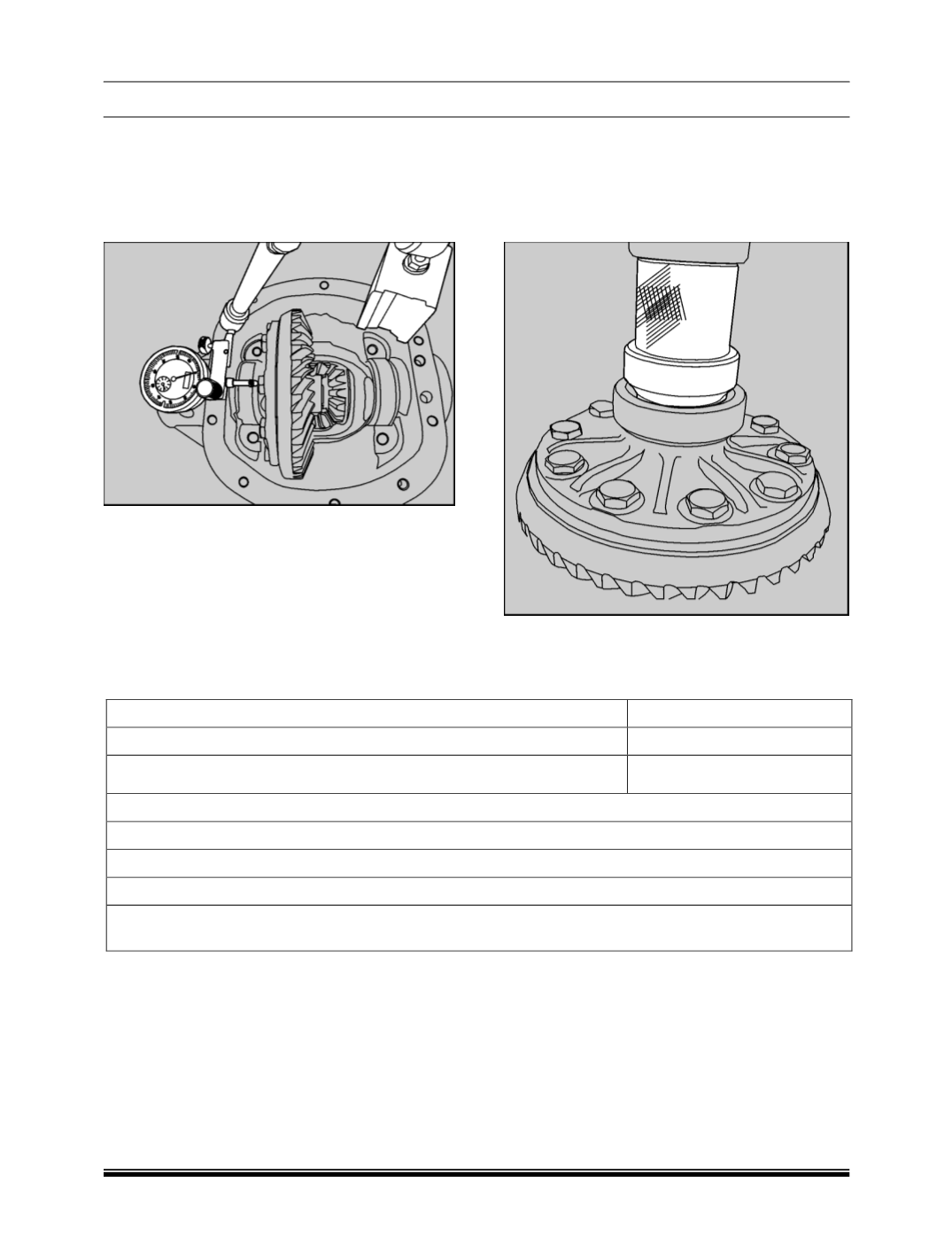
22.Place differential assembly into housing. Install
dial gauge and locate tip of indicator on the
surface of one of the ring gear screws. Force
differential case assembly away from pinion
gear. With force still applied set indicator at 0
(Zero)
.
23.Force differential case assembly and ring gear
to mesh with pinion gear.
24.Rock the ring gear to allow teeth to mesh
Repeat to obtain a stable reading. Record in
given format as B.
25.Remove indicator and master differential
bearings. Install side bearing on differential
assembly
using
installer
(Part
No.270458903325)
and place bearing cup
along with selected shim pack in between side
bearing and carrier assembly.
26.Repeat this procedure for installation of shims /
bearing cone on opposite side of differential
case.
1. Total amount of space measured without ring gear.
Measurement A =………
2. Total amount of space measured with gear. set assembled in carrier
Measurement B=………
3. Measurement A minus Measurement B dimensions
Measurement C =………
Assemble shim pack using dimension determined in A, B, C adjusting the packs as described below.
RING GEAR SIDE
Assemble shim pack to measurement B- 0.125mm or B- 0.005”
OPPOSITE SIDE OF RING GEAR:
Assemble shim pack to measurement C. Add shim thickness 0.20 mm or 0.008” for differential bearing
preload and backlash.