


 1450 / 1863

ELECTRICAL
148
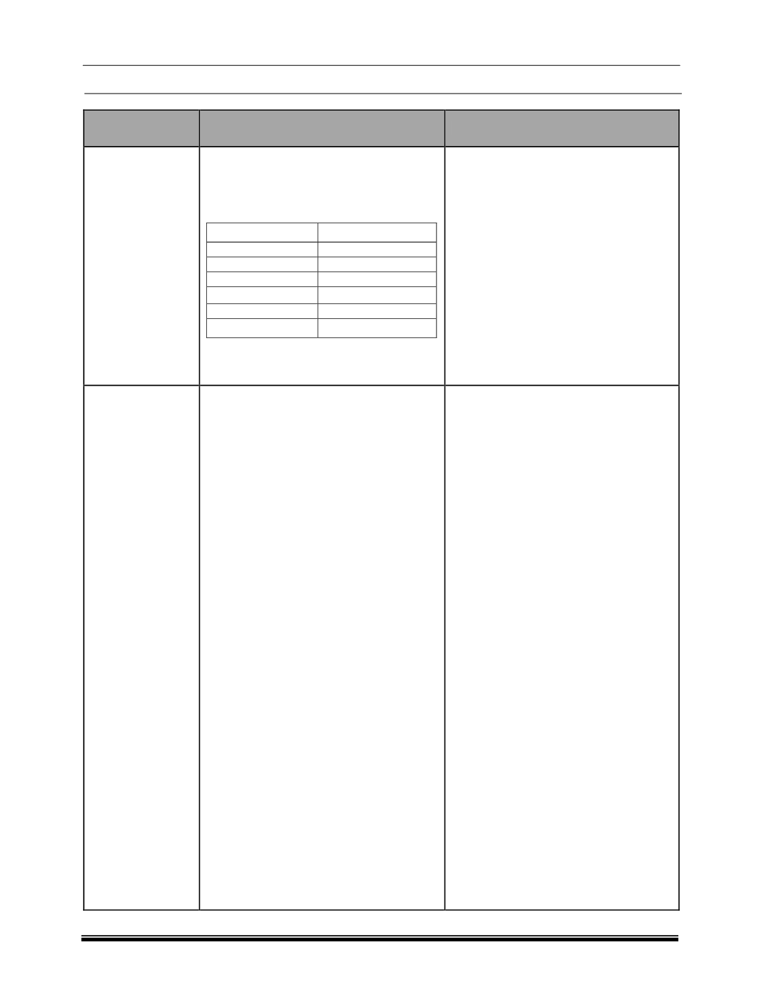
Failure Condition
Possible Root Cause
To be checked
No Drive mode
selection
information on the
DCS(All AMBER
LED OFF )
Loose connection in the Drive control
switch connector
Pin Description
Pin No
Battery
1
GND
5
IGN
3
Wake up
4
CAN_H
8
CAN_L
6
1. Tighten the connectors if required
2. Check for the battery voltage.
3. Check for TBO (terminal back out).
4. MO (mouth open) for terminals in this
connector.
All function ON
LED's on the
switch glowing in
AMBER Color and
Instrument cluster
shows
AUTO
mode not able to
select the Drive
mode
I.RAM Failure
II. Mode selector Sw failure
III. Validation logic outcome
invalid/function failure
IV. BCM
Message
Timeout/DLC
V. ESP
Message
Timeout/DLC
VI. ABS
Message
Timeout/DLC
VII. TOD
Message
Timeout/DLC
VIII. EMS
Message
Timeout/DLC
IX. IC
Message
Timeout/DLC: To be
defined by TML for variant
selection
X. Error Passive
XI. Bus-Off
XII. Range or implausible
failure of BCM Msg
XIII. Range or implausible
failure of ESP Msg
XIV. Range or implausible
failure of ABS Msg
XV. Range or implausible
failure of TOD Msg
XVI. Range or implausible
failure of EMS Msg
XVII. Range or implausible
failure of IC Msg
XVIII. Under Voltage
XIX. Over Voltage
Read Freeze Frame data for DID
B193D-01. exact issue prescription
regarding DCS will be available there.
take actions as per that freeze frame
data and then clear the fault.