


 1455 / 1863

ELECTRICAL
153
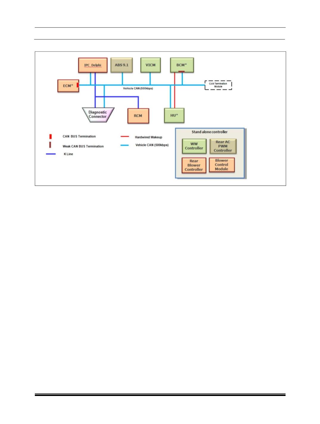
NETWORK TOPOLOGY: XE VARIANT
CAN termination resistance of can bus is in EMS
and IC. bus is EMS (
Engine management system
)
& IC (Instrument Cluster)
List of ECU’s connected to CAN bus through
CAN stub:
ABS (
Anti lock braking system
)/ ESP
(
Electronic stability program
)
SAS (
Steering angle sensor
)
YRS (
Yaw rate sensor
)
FATC (
Fully automatic temp controller
)
IMMO(
Immobilizer
)
TOD (
Torque on demand
)
IC (
Instrument cluster
)
HU (Head Unit)
BCM (Body Control Module)
EMS (Engine Management System)
PDC (Park Distance Controller),
TCU (Transmission control Unit)
Immo (Immobilizer)
NOTE:
YRS is connected on private CAN bus, i.e.
Separate CAN bus the in between ESP and YRS
SAS & YRS are part of ESP system not for ABS
system.
List of K line Diagnostic ECU’S:
ABS (Anti lock braking system)/ ESP
(Electronic stability program)
FATC (Fully automatic temp controller)
TOD (Torque on demand)
WWCONT (Window winding controller)
IPC Delphi
NOTE:
1.Manual HAVC system having blink code
diagnostic method not through K-line.
List of Standalone ECU’s:
Rear view Camera
RLS(Rain
light sensor
)
RR BLOW. CONT. (
Rear blower controller
)
Mood Lamps / Modules
PWM Controller for rear blower
PRND module
Blower Control Module