


 1452 / 1863

ELECTRICAL
150
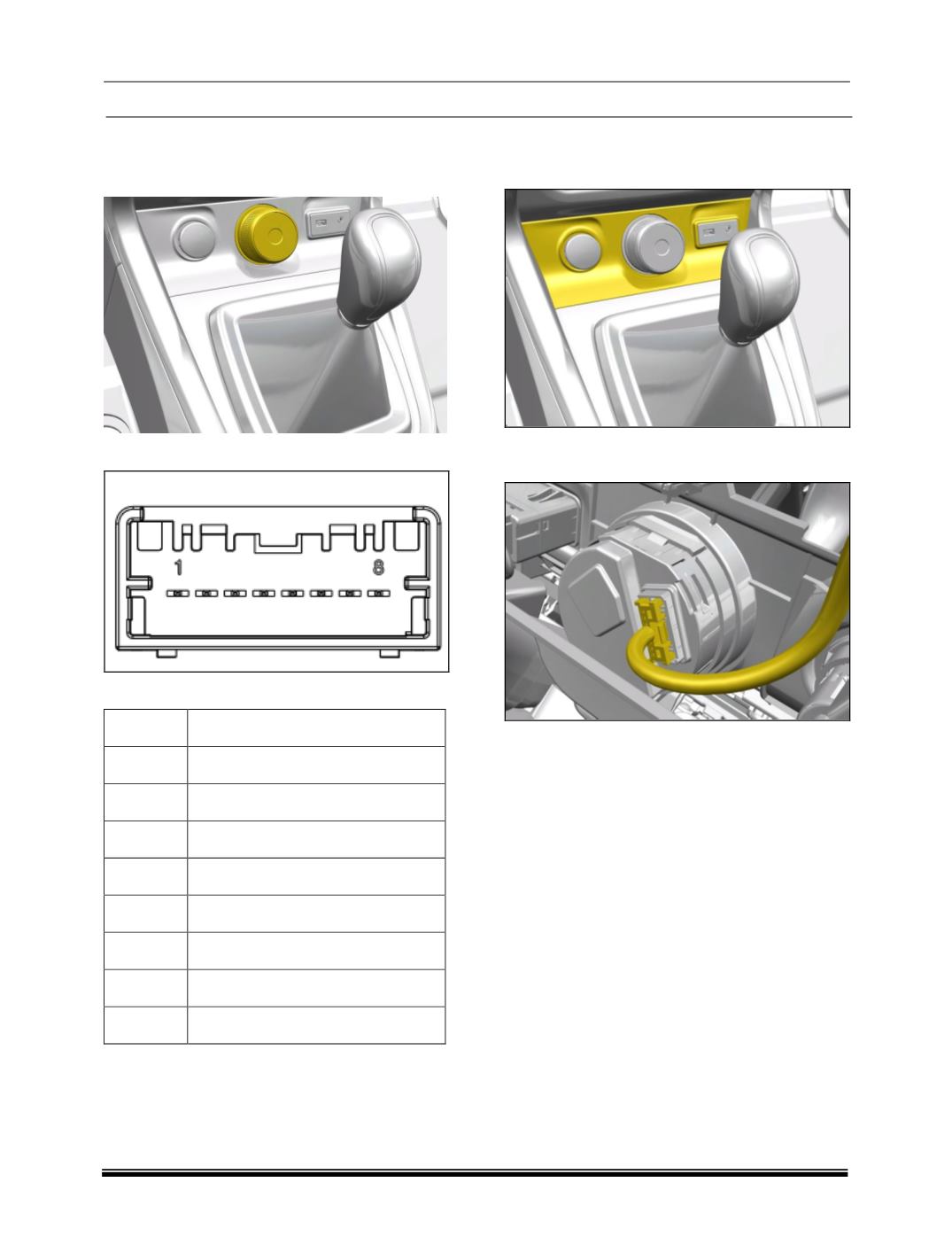
LOCATION
The Drive Control Switch is mounted at the
bottom most position of the center fascia.
CONNECTOR DETAIL
PINOUT DETAIL
PIN NO.
DESCRIPTION
1
BATT
2
NO CONNECTION
3
IGN SW
4
WK UP
5
GND
6
CAN L
7
NO CONNECTION
8
CAN H
REMOVAL
1. Remove the bezel from IP.
2. Disengage the connector from Drive Control
Switch.
3. Press the locked snaps on the bezel outwards
and push the switch out from connector side.
INSTALLATION
1. Insert the switch in Bezel cutout.
2. Connect the vehicle side connectors to the
DCS.
3.
Insert the Bezel on the center fascia