


 1508 / 1526

19
BODY
14. REMOVAL/INSTALLATION OF FENDER
(Fig. 19 &
20)
REMOVAL
l
Open the bonnet.
l
Disconnect side indicator connection and remove
the side indicator lamp by removing the spring
clip from under bonnet at RH and LH sides.
l
Remove the front bumper. Refer “Removal/
Installation of front bumper”.
l
Remove the side mould over the wheel arch.
Refer removal installation of plastic moulds.
l
Remove the rubber pads on fender top channel.
l
Remove the mounting screws on fender (five on
top, one front screw, one rear bottom screw and
two rear middle screws) and remove the fender.
INSTALLATION
l
Mount the fender in position and fix the mounting
screws.
l
Fit the side mould on wheel arch.
l
Fix the side indicators by securing the spring clips.
l
Mount the front bumper. Refer 'Removal/
Installation of front bumper'.
l
Fix the rubber pads on top fender channel for
supporting bonnet.
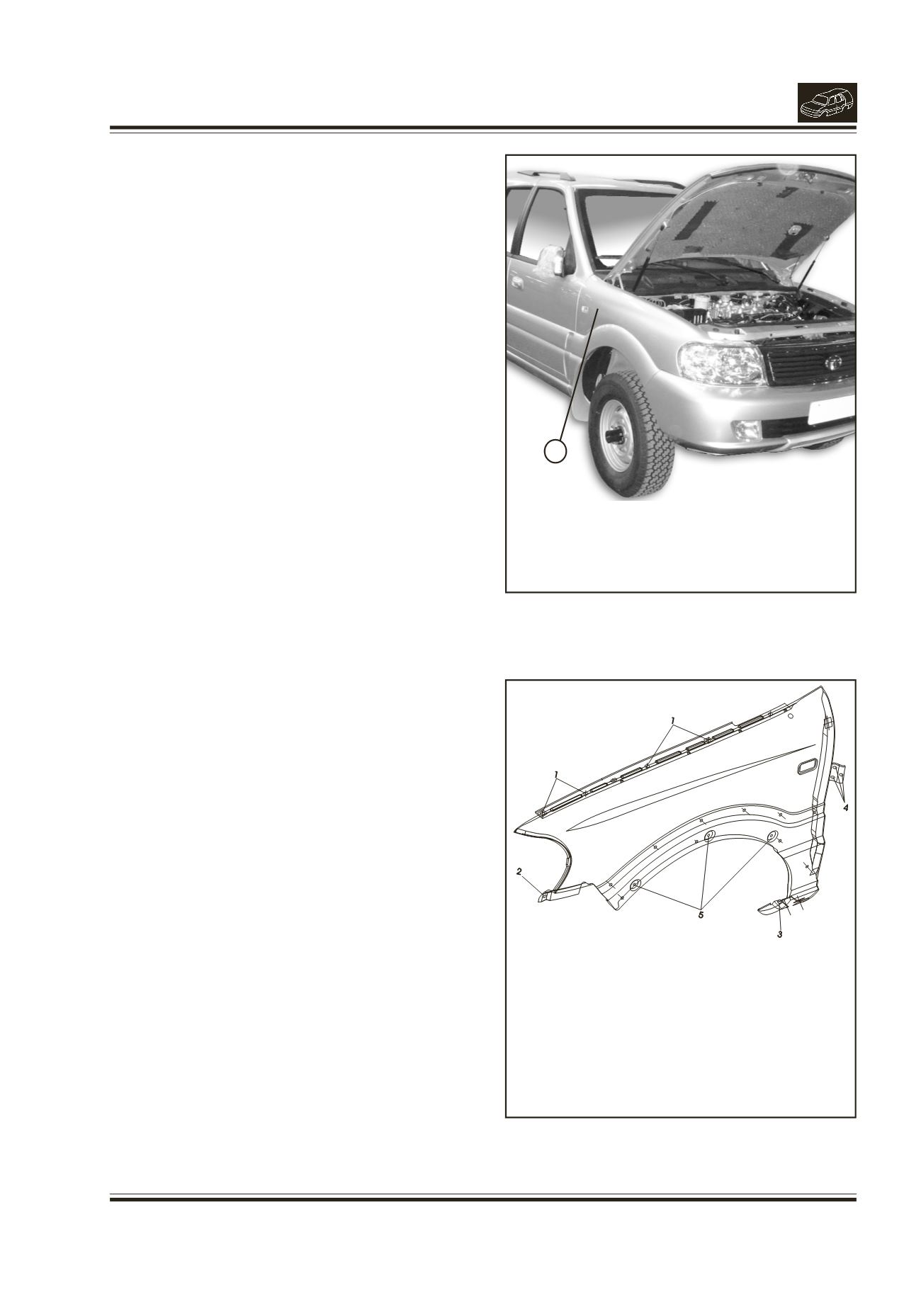
Fig. 19.
1.
FENDER
Fig. 20.
1.
LOCATION OF TOP MOUNTING SCREWS
2.
LOCATION OF FRONT MOUNTING SCREW
3.
LOCATION OF REAR BOTTOMMOUNTING SCREW
4.
LOCATION OF REAR MIDDLE MOUNTING SCREWS
5.
BUTTON LOCATION FOR MUD FLAP
1