


 1503 / 1526

14
BODY
9. REMOVAL/INSTALLATION OF DOOR LATCH
(Fig.
11 & 12)
REMOVAL
l
Remove the inner trim
l
Pull out required portion of plastic membrane.
l
Disconnect links and electrical connections from
door latch micro switch.
l
Remove 3 mounting screws, washers and latch.
l
Remove latch.
INSTALLATION
l
Locate latch on door.
l
Install 3 washers (C6.4), 3 sl. csk. screws (M6x16)
and tighten the screws.
l
Connect links properly.
l
Connect electrical connection of micro switch.
l
Ensure proper functioning of latch.
l
Apply sealant (Butyl mastic) on the door inner
panel and fix plastic membrane on it.
l
Fit the inner trim.
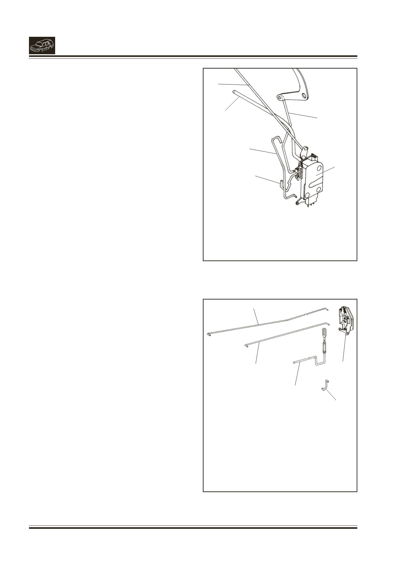
Fig. 11.
1. LINK (BELL CRANK TO LATCH)
2. LINK OUTER HANDLE
3. LINK INNER HANDLE
4. LINK SOLENOID
5. LINK LOCK BARREL
6. LATCH FRONT DOOR
2
1
3
4
5
6
Fig. 12.
1.
LINK LOCKING KNOB
2.
LINK INNER HANDLE
3.
LINK OUTER HANDLE
4.
LINK SOLENOID
5.
LATCH REAR DOOR
1
2
3
4
5