


 1251 / 1526

ENGINE
83
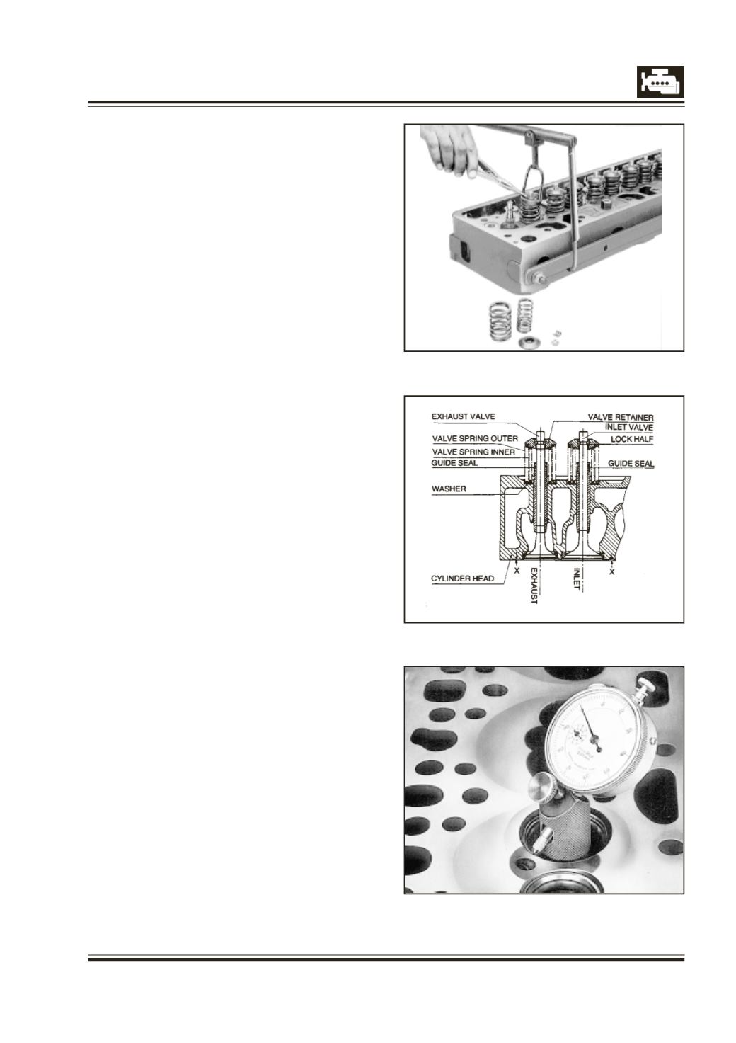
Fig. 2
Fig. 1
Fig. 3
VALVES, VALVE GUIDES, VALVE SPRINGS, VALVE
SEATS
REMOVAL OF VALVES
(Cylinder head removed)
1 Place cylinder head on two suitable wooden
supports.
2 Press springs with help of valve spring compressor,
312 589 02 31 and support rail 312.589 03 31 duly
counter-supporting poppet of valve to be
removed. Fig. 1.
3 Remove lock halves from valve stem and remove
them out.
4 Remove spring retainer, springs and guide seal.
5 Remove washer between springs and cylinder
head.
6 Similarly remove remaining valves.
INSTALLATION OF VALVES
1 Clean valves, washers, springs, retainers and lock
halves.
2 Place cylinder head on two suitable wooden
supports.
3 Insert washer and springs.
4 Lubricate valve stem. Insert valve from below into
cylinder head. Install guide seal.
5 Place spring retainer over springs and compress
(after counter supporting poppet of valve to be
assembled) with support rail, 312 589 03 31 and
valve spring compressor, 312 589 02 31. Insert lock
halves with smaller diameter towards lower side
evenly in spring retainer and release pressure on
valve spring. Lift cylinder head and slightly tap
valve stems with a mallet to ensure that lock halves
have locked valve and spring retainer properly.
Take care that two halves are centrally located.
NOTE :
Ensure that distance from valve head to cylinder head
parting surface is within specifications.
6 Similarly install remaining valves.
MACHINING OF VALVE SEATS
Before proceeding for machining of valve seats, check
for following
a. Check guide bores for wear with ‘GO NO GO’
gauge, 636 589 00 21 for inlet valve guide bore
and 2576 5890 02 03 for exhaust valve guide bore.
Replace valve guides if ‘NO GO’ gauge passes
through bore.
b. Ensure that concentricity between valve seat and
valve guide bore is maintained within specified
limits. Fig. 3.