
BODY
10
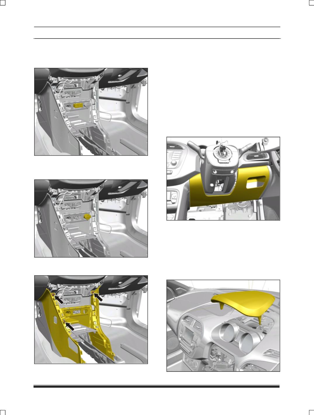
10.Disconnect USB auxin connectivity module
Assembly. (For removal refer USB auxin
connectivity module removal process in
Electrical section.)
11.Disconnect complete power socket assembly.
(For removal refer
power socket assembly
removal process in Electrical section.)
12.Remove all front floor console mounting
screws.
13.Remove all push rivets and clips of front
console and take it out.
FITMENT
For fitment follow the reverse procedure of
removal.
9.2.3 DASHBOARD
REMOVAL
With Cross Car Beam
1. Remove steering wheel with Driver air bag (if
applicable) (For procedure refer steering wheel
removal process in steering section.)
2. Pull out Driver lower panel.
3. Remove nacelle Assembly. (For removal refer
steering column removal process in steering
section.)
4. Remove combination switch assembly and
ignition switch assembly (For procedure refers
combination switch and ignition switch removal
process in Electrical section.)
5. Pull out instrument cluster hood.


