


 218 / 310

ENGINE
172
TIGHTENING TORQUE
DESCRIPTION TORQUE
Hex screw M4 x16 0.66 Kgfm
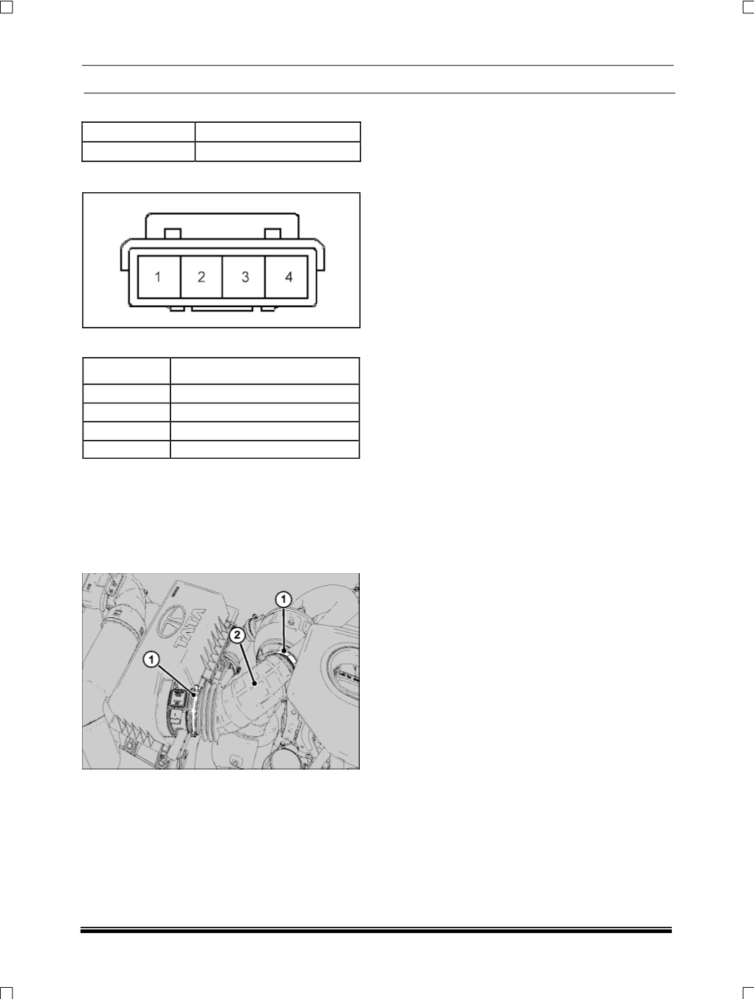
CONNECTOR DETAILS
PIN OUT DETAILS
PIN NO
DESCRIPTION
1
Air mass flow input
2
Air inlet temperature input
3
Air mass flow return
4
Air mass flow sensor supply
REMOVAL
1. Disconnect the wiring harness connector from
sensor.
2. Remove the connecting hose (
sensor housing to
turbocharger
) (
2
) from sensor housing by un-
clamping the hose clamps (
1
) with help of plier.
3. Remove two mounting screws of sensor assem-
bly and take out from its location along with
rubber sealing ring.
INSPECTION
With Ignition 'ON',
•
Check Output Voltage between Pin 3 (
MAF
) and
Pin 5 (
GND
).it should be between 0 to 1 V.
•
Check Output Current between Pin 1 (
U
b
) and
Pin 5 (
GND
).it should between 35 and 55 mA.
NOTE
Check the SIMAF Sensor with no mass flow. The
above given values are for zero mass flow.
REFITMENT
1. Locate sensor assembly in the air filter housing
along with the rubber sealing ring and fit two
mounting screws.
2. Fit the connecting hose (
sensor housing to turbo-
charger
) and fit the hose clamp.
3. Connect the wiring harness connector to the sen-
sor.
NOTE
Ensure that no damage to the rubber hose while re-
moving and re-fitment.