


 213 / 310

ENGINE
167
SENSORS AND ACTUATORS DETAILS
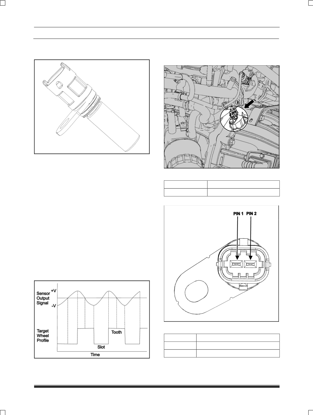
1. CRANK ANGLE SENSOR
The crank angle sensor is a magnetic field sensitive
transducer and generates a voltage output propor-
tional to the rate of change of the magnetic field near
a "Missing tooth" configuration. It monitors the rotat-
ing speed (
rpm
), the position of crankshaft/ piston
and speed fluctuations of the engine and gives con-
tinuous feedback to the ECU. In other words it gives
engine speed and piston position signal to the ECU.
The sensor gap should be 0.3 to 1.7 mm. If the gap
between the flywheel and crank angle sensor is not
correct, the engine will not start or may misfire.
Intended Target wheel is uniformly cut with 60 teeth
and 2 teeth removed ideally between 120 & 90 de-
grees BTDC i.e. in a region where it is unlikely
Injection events shall be scheduled. The sensor will
measure a rotating feature (
target wheel
) by sensing
teeth/slot patterns and process this information into a
positive going voltage, zero crossing and negative
going voltage pulse for each teeth/slot that passes
below the sensor tip.
LOCATION
The crank angle sensor is fitted on the clutch hous-
ing.
TIGHTENING TORQUE
DESCRIPTION
TORQUE
Hex bolt M6 x16 0.4 to 0.6 Kgfm
CONNECTOR DETAILS:
PIN OUT DETAILS
PIN NO
DESCRIPTION
1
Crank shaft sensor(+)
2
Crank shaft sensor(-)