


 223 / 310

ENGINE
177
11. ACCELERATOR PEDAL SENSOR
This sensor is secured to the accelerator pedal in-
side it contains an axially-located shaft connected to
two potentiometers: a main one and one safety one.
A coil spring on the shaft ensures the correct amount
of resistance to pressure while a second spring en-
sures return following release.
The redundant signal reading makes it possible to
continuously monitor the plausibility of the readings
in order to guarantee complete safety whilst driving
even if there is a failure.
The accelerator pedal position is converted into an
electrical voltage signal and sent to the EMS ECU by
the potentiometer connected to the pedal. The ac-
celerator pedal position signal is processed together
with the information relating to the engine rpm to
produce the desired torque and engine speed.
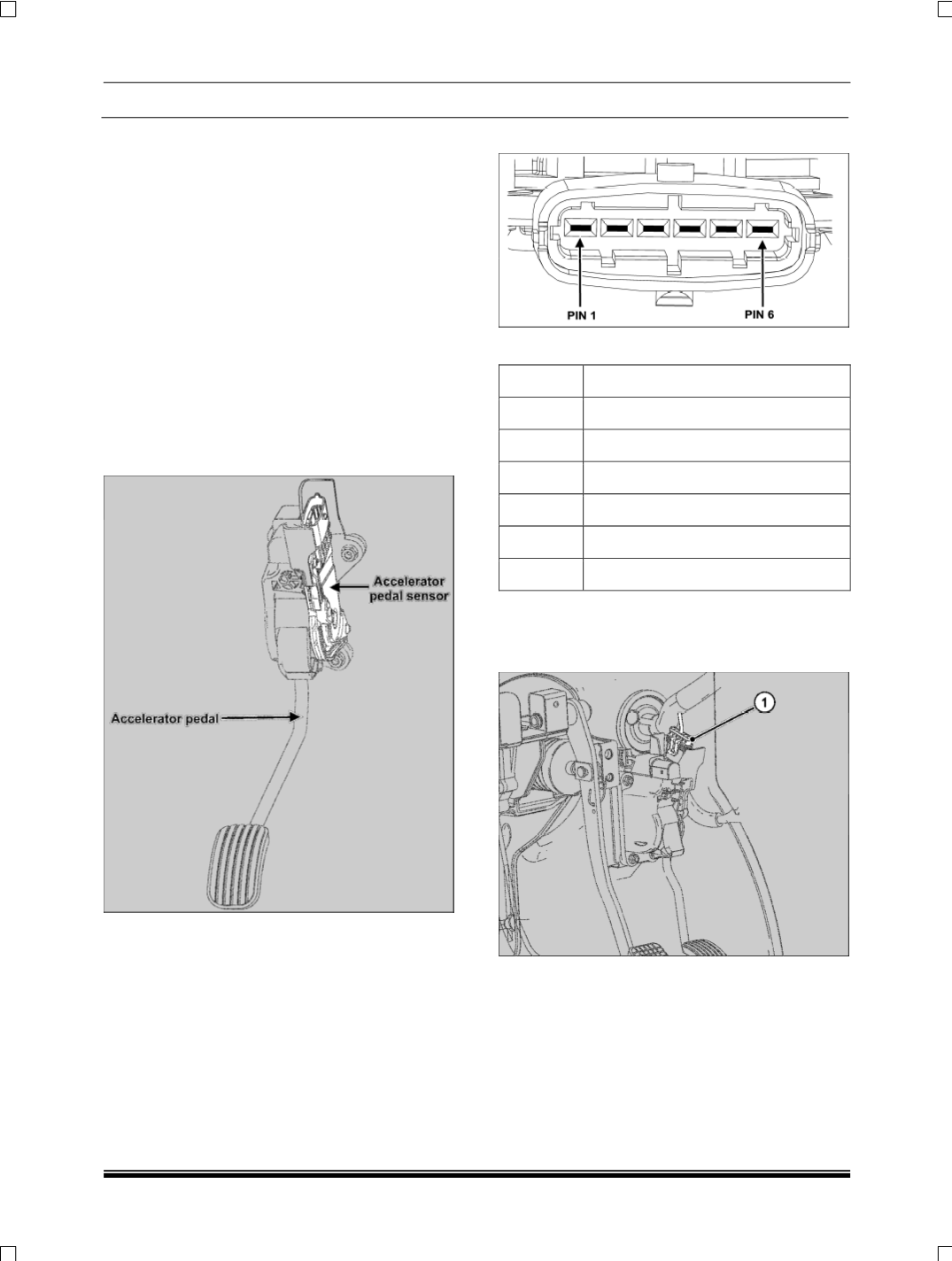
CONNECTOR DETAILS
PIN OUT DETAILS
PIN NO DESCRIPTION
1
Acc pedal Sensor 2 supply
2
Acc pedal Sensor 1 supply
3
Acc pedal Sensor 1 return
4
Acc pedal Sensor 1 signal
5
Acc pedal Sensor 2 return
6
Acc pedal Sensor 2 signal
REMOVAL
1. Disconnect the accelerator pedal electrical con-
nector (1) from the accelerator pedal module.