


 214 / 310

ENGINE
168
REMOVAL
1. Remove LH wheel assembly.
2. Remove wheel-arc inner cover.
3. Disconnect the connector from crank position
sensor.
4. Remove one mounting bolt.
5. Take out the crank position sensor.
INSPECTION
Measure resistance across the terminals pin 1 & 2
using Digital multimeter it should be 2400 Ohms ±
240 at 25 °C.
REFITMENT
1. Locate the sensor on clutch housing and fit one
mounting bolt with specified tightening torque.
Tightening torque for Bolt – 0.4 to 0.6 Kgfm.
2. Connect wiring harness connector to the crank
position sensor.
3. Fit the wheel-arc inner cover.
4. Fit the LH wheel assembly.
NOTE
While fitment of crank position sensor specified air
gap to be maintain. (Air gap 0.30mm to 1.7mm)
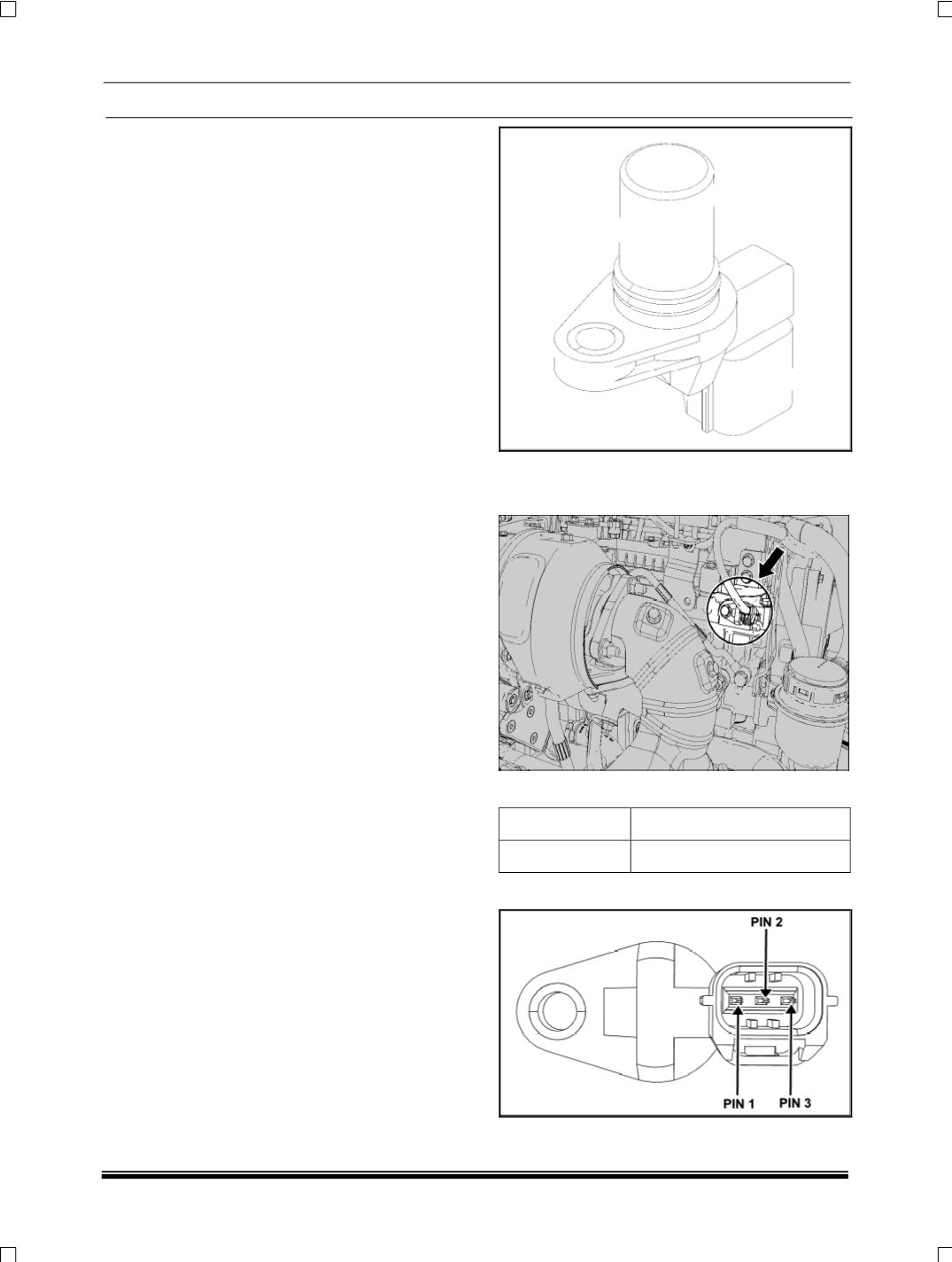
2. CAM SENSOR
The cam sensor is a magnetic field sensitive trans-
ducer and generates a voltage output proportional to
the rate of change of the magnetic field near a "cam-
shaft lobe" configuration. The cam sensor senses the
position of the flag on the Exhaust camshaft and
gives feed back to the ECU regarding the cylinder
No.1 (
90º BTDC
). The sensor gap should be 1.7 mm.
If the gap is not correct and also the position of cam-
shafts with respect to crank shaft (
set
during
assembly
), the engine will not start or may misfire.
While the engine is running & the cam sensor fails
then the engine will continue to run till the engine will
stop & will not start again.
LOCATION
The cam sensor is fitted on cylinder head
.
TIGHTENING TORQUE
DESCRIPTION
TORQUE
Hex bolt M6
1 Kgfm
CONNETCOR DETAILS
PIN DETAILS