


 217 / 310

ENGINE
171
RESITANCE VS TEMPERATURE CHART
Measure resistance between Pin no. 3 & 4 at various
temperature given in below table.
T [°C] Rnom [
Ω
]
Tolerance
Rmin [
Ω
]
Tolerance
Rmax [
Ω
]
-10
9202
8716
9689
0
5774
5497
6050
10
3714
3553
3875
20
2448
2353
2544
80
315.8
310.0
321.6
100
182.8
180.4
185.1
REFITMENT
1. Locate the TMAP sensor on intercooler outlet and
fit one mounting bolt.
2. Connect the electrical connection to the TMAP
sensor.
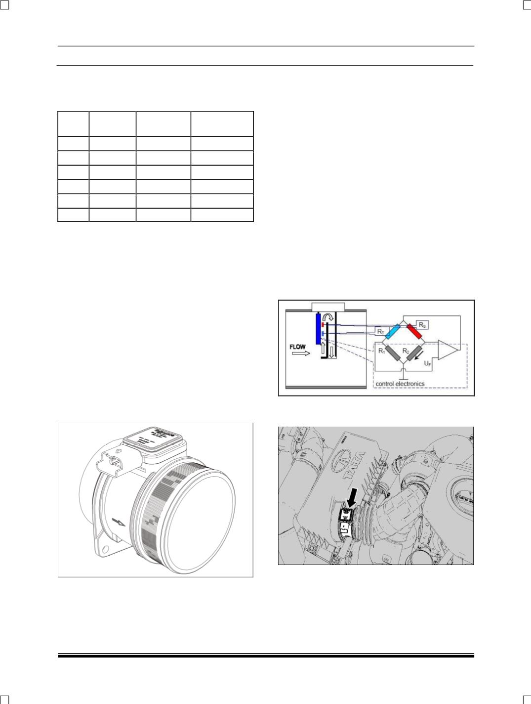
4. SIMAF SENSOR (
Siemens Integrated Mass
Airflow Sensor
)
This sensor gives Information about the amount of
air quantity and temperature of the air entering in the
engine. This input is used by the ECU for corrections
of fuel quantity based on amount of air availability for
optimization of exhaust gas circulation & the turbo-
charger control.
NOTE
While assembling, the AMF sensor the point of the
arrow should be towards the Turbo charger.
The operating principle is based on the heating of a
diaphragm (
sensitive
element
containing
two
re-
sistances upstream and downstream of the support
)
in a by-pass duct through which the engine intake air
flows.
Two temperature dependent metal film resistors on
thin glass substrates are mounted in the SIMAF flow
channel. The resistors are connected with fixed re-
sistors R1 and R2 in a bridge circuit. The bridge is
balanced so that the control electronics heat RS to a
fixed temperature differential relative to the intake
air. The sensing resistor RT compensates for intake
air temperature variations, holding the constant tem-
perature offset of RS. The intake airflow converts
heat from RS and the heating current must be dy-
namically increased by the control electronics to
maintain the fixed offset temperature. The current
flowing through RS is a measure for the mass airflow
and can be measured as a voltage drop across the
fixed resistor R2. This signal is processed by the
sensor and is output as either an analog or frequen-
cy signal.
NOTE
The flow meter measures the air mass directly (not
the volume) to eliminate problems of compensation
correlated to the temperature, altitude, pressure val-
ues etc
.
LOCATION:
This sensor is mounted between air
filter and turbocharger.