


 992 / 1428

TRANSAXLE
131
Installation:
NOTE
Verify that the gearbox is in neutral gear
position, because the ‘Mechatronic Gear
Actuator’ spare-part is provided in this position,
otherwise rotate the gearbox command lever by
hand to achieve the position corresponding to
the spare-part before mounting.
1. In order to guarantee right ‘Mechatronic Gear
Actuator’ translation during the mounting, to
avoid O-rings damages, screw ‘Special tool –
guide rods’ φ6x100 mm length, with 15 mm
threaded M6, in the ‘Power Unit Base Plate’
holes used by right ‘Mechatronic Gear
Actuator’ fixing screws and shown in the
picture below.
2. Remove traces of oil from the ‘Power Unit
Base Plate’ seal surface in contact with the
spare gasket, with care to avoid
contamination from foreign materials (dust,
metal burrs, etc…) or surface damages.
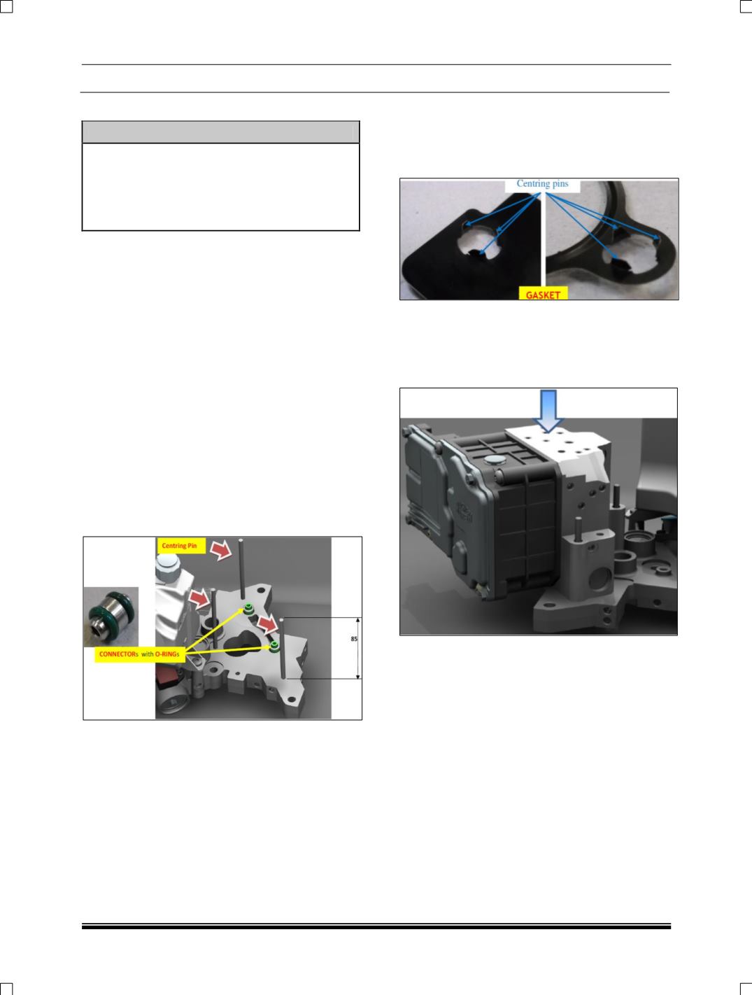
3. Assemble the new O-rings on the new
connectors (see the detail on below picture).
4. Mount the new connectors with O-rings in
their ‘Power Unit Base Plate’ seats (see
picture below), after lubrication with new ‘CS
Speed’ oil.
5. Lubricate with new ‘CS Speed’ oil the
‘Mechatronic Gear Actuator’ seats for
connectors with O-rings.
6. Assemble the ‘New Gasket’ on the new
‘Mechatronic Gear Actuator’ with the correct
orientation, inserting the centering pins into
the fixing holes of the ‘Mechatronic Gear
Actuator’ body.
7. Position the ‘Mechatronic Gear Actuator’ with
gasket over the ‘Power Unit Base Plate’,
using for reference the ‘Special tool – guide
rods’ and moving it parallel towards the
mating surface.
8. When the ‘Mechatronic Gear Actuator’ body
seats come in contact with O-rings push it
slowly with appropriate load to complete the
assembly.
9. Unscrew the ‘Special tool – guide rods’ and
screw without tighten the three screws for
fixing the ‘Mechatronic Gear Actuator’ on
‘Power Unit Base Plate’.